Typical deployment for VMware Aria Operations in CA mode includes 2, 4, 6, or 8 nodes based on the appropriate sizing requirements.
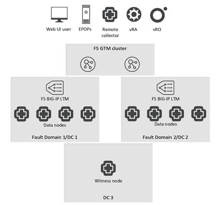
Those nodes must be deployed equally into two independent datacenters. One added witness node must be deployed in a third independent datacenter. Each datacenter is then grouped in a Fault Domain example FD #1 and FD #2. To distribute the traffic between nodes in a Fault Domain, we also need to configure a LTM appliance for each FD (two in total) by following the instructions in this guide.
Since a GTM device primarily handles dynamic DNS record updates, we need to plan the DNS naming before the deployment of the Fault Domains. We also need to ensure all of the DNS records are included into the VMware Aria Operations SSL certificate – at this point, the installer will not include the address of the LTM VIPs or GTM Wide-IPs; therefore, it will be required to issue and sign (either with external trusted CA or internal one) a new certificate.
In the example below, there are 4 data nodes per Fault Domain, 2 LTM VIPs and, 1 GTM Wide-IP. The idea behind this structure is to allow access to the GTM Wide-IP which is globally distributed hence it will point to either FD #1 or FD #2 depending or the current availability (you can also choose to use latency based traffic redirection so a user will be sent to the closest available FD) or access a given FD directly by its LTM VIP for debugging purposes or as a last resort fail-safe.
Name |
Type |
ADDRESS |
|---|---|---|
vrops-node1.dc1.example.com |
A |
IP |
vrops-node2.dc1.example.com |
A |
IP |
vrops-node3.dc1.example.com |
A |
IP |
vrops-node4.dc1.example.com |
A |
IP |
vrops-node5.dc2.example.com |
A |
IP |
vrops-node6.dc2.example.com |
A |
IP |
vrops-node7.dc2.example.com |
A |
IP |
vrops-node8.dc2.example.com |
A |
IP |
vrops-fd1.dc1.example.com |
A |
LTM VIP |
vrops-fd2.dc2.example.com |
A |
LTM VIP |
vrops.example.com |
Wide-IP/A |
To be configured later in this chapter |
The architecture must look similar to the diagram below:

After deploying nodes in each FD and configuring the respective LTM load-balancers, we can proceed with the configuration of the GTM nodes. The GTM cluster itself can be deployed in any architecture supported by F5. For our testing, we have used a GTM + LTM combined virtual appliances deployed in each datacenter. We have also clustered only the GTM module since there is no need for clustering on the LTM level. Having separate GTM and LTM appliances or physical systems is supported.
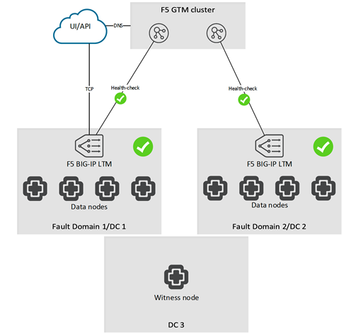
A fully configured and deployed solution during normal operation:

Having the LTMs monitoring each individual VMware Aria Operations nodes and the GTMs monitoring the accessibility of the entire Fault Domain, ensures the maximum possible fault protection with the least possible overhead.
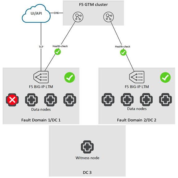
In case there is only a single node failure in a Fault Domain, the local LTM will prevent any traffic hitting the affected node while the entire Fault Domain will continue to remain functional
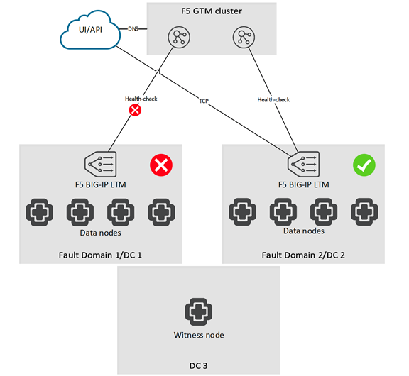
In case, we experience an outage in the entire datacenter, the GTMs will re-route the traffic to a healthy datacenter
Failover and recovery are automatic in both scenarios

