


This section discusses Layer 3 DSR in detail.
L3 DSR can be used with a full proxy deployment:
Tier 1: L3 DSR
Tier 2: Full-proxy (with SNAT)
Supported mode: IPinIP
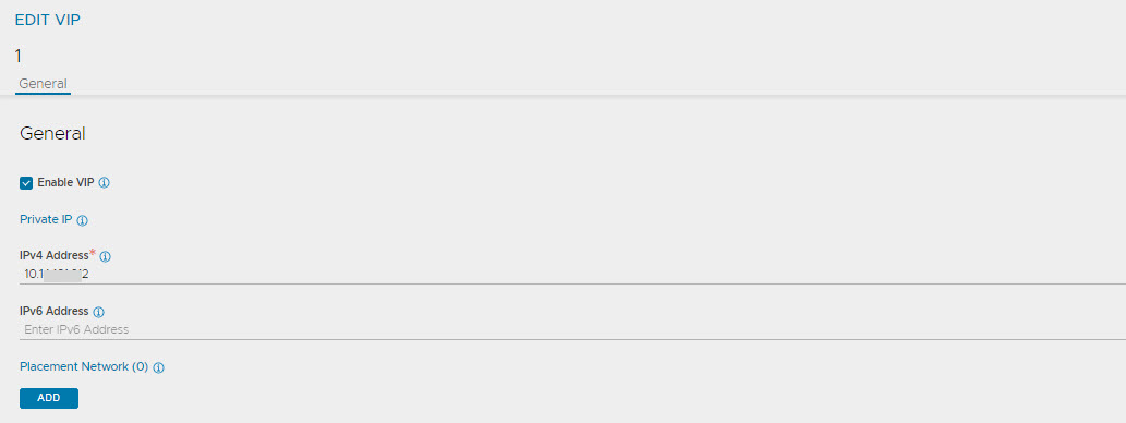
Virtual service placement is supported in the front-end using BGP.
Supported load balancing algorithm: Only consistent hash is supported.
Deployment mode: Auto gateway and traffic enabling must be deactivated for the deployment mode when Layer 7 virtual service is configured (in the deployment mode Tier-2 as shown below).
If the SEs are scaled out in the Tier-2 deployment mode, pool members are added manually once new SEs are added.
Starting with Avi Load Balancer 30.2.1 version, L3 DSR is supported in OpenStack for IPv6 (and IPv4).
Packet Flow Diagram
The following diagram exhibits a packet flow diagram for Layer 3 DSR:
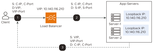
IP-in-IP tunnel is created from the load balancer to the pool members that can be a router hop(s) away.
The incoming packets from clients are encapsulated in IP-in-IP with source as the Service Engine’s interface IP address and destination as the back-end server IP address.
In the case of the Generic Routing Encapsulation (GRE) tunnel, the incoming packets from clients are encapsulated in a GRE header, followed by the outer IP header (delivery header).
Deployment Modes
Tier-1
Layer 4 virtual service is connected to application servers which terminate the connections. Pool members are the application servers.
Servers handle the IPinIP packets. The loopback interface is configured with the corresponding virtual service IP address. The service listening on this interface receives packets and responds to the client directly in the return path.
In case of tier-1 DSR, the backend application servers must listen on all the virtual service listening ports.
Tier-2
Layer 4 virtual service is connected to the corresponding Layer 7 virtual service (which has the same virtual service IP address as Layer 4 virtual service), which terminates the tunnel.
Layer 4 virtual service’s pool members will be Service Engines of the corresponding Layer 7 virtual services.
For the Layer 7 virtual service, traffic is disabled so that it does not perform ARP.
Auto gateway is disabled for Layer 7 virtual service.
Servers are Service Engines of corresponding Layer 7 virtual service.
Packet Flow
IPinIP packets reach one of the Service Engines of Layer 7 virtual service. That SE will decrypt and handle the IPinIP packet and give it to the corresponding layer 7 virtual services. The virtual service sends it to the backend servers.
Return packets from the backend servers are received at the virtual service, and the virtual service forwards the packet directly to the client.
The following diagram exhibits packet flow for the tier-2 deployment in the Layer 3 mode:
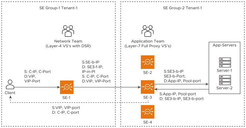
The following are the observations for the above deployment as mentioned in the diagram:
Layer 4 virtual service is connected to the corresponding Layer 7 virtual service (which has the same virtual service IP address as Layer 4 virtual service), which terminates the tunnel.
Layer 4 virtual service’s pool members will be Service Engines of the corresponding Layer 7 virtual services.
For the Layer 7 virtual service, traffic is disabled so that it does not perform ARP.
Auto gateway is disabled for Layer 7 virtual service.
Servers are Service Engines of corresponding Layer 7 virtual service.
Return packets from the back end servers are received at the virtual service, and the virtual service forwards the packets directly to the client.
Creating Virtual Service and associating it with the Network Profile (for Tier-2 deployment)
Navigate to and click CREATE to add a new virtual service. Provide the following information as mentioned:
Provide the desired name for the virtual service and IP address.
Select the network profile created in the previous step for Tier-2 deployment from the TCP/UDP Profile drop-down menu.
Select the pool created for the selected virtual service.
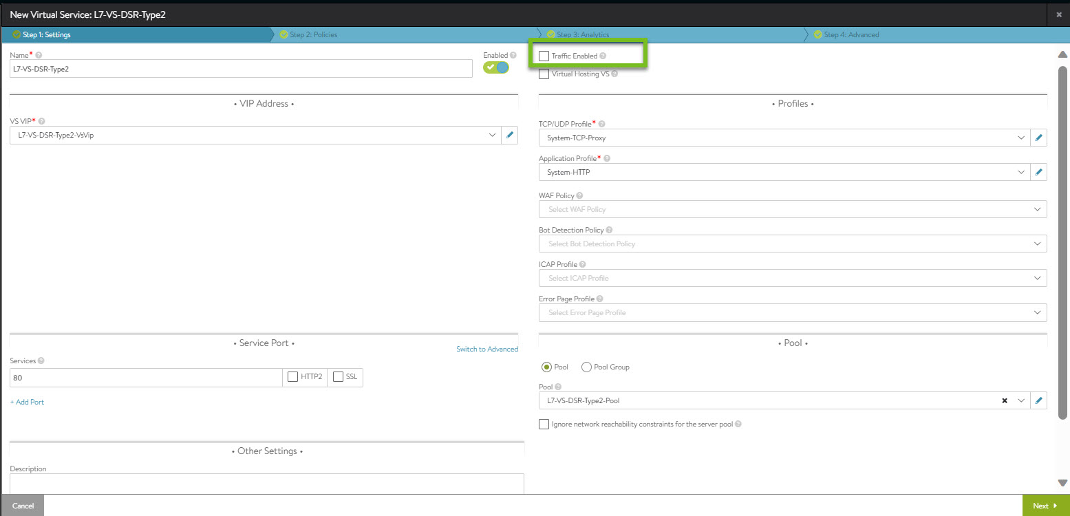
The Traffic Enabled check box must not be selected for Tier-2 deployment.
Configuring Server
modprobe ipip

ifconfig tunl0 <Interface ip of the server, same should be part of
pool> netmask <mask> up

ifconfig lo:0 <VIP ip> netmask 255.255.255.255 -arp up
echo 1 > /proc/sys/net/ipv4/conf/all/arp_ignore
echo 2 > /proc/sys/net/ipv4/conf/all/arp_announce
echo 2 >/proc/sys/net/ipv4/conf/tunl0/rp_filter

sysctl -w net.ipv4.ip_forward=1
Configuring the Loopback Interface for Windows
The following commands must be configured on the server to make the HTTP health monitor work for Windows servers in the back end:
netsh interface ipv4 set interface "Ethernet0" forwarding=enabled netsh interface ipv4 set interface "Ethernet1" forwarding=enabled netsh interface ipv4 set interface "Ethernet1" weakhostreceive=enabled netsh interface ipv4 set interface "Loopback" weakhostreceive=enabled netsh interface ipv4 set interface "Loopback" weakhostsend=enabled
In the above steps,
Ethernet0 = Management interface name
Ethernet1 = Data interface name
Loopback = Loopback interface name (VIP)
