


Avi Load Balancer on Linux server (bare metal) cloud supports port channel (bond) interfaces. A port channel interface groups multiple physical interfaces into a single logical interface and provides fault tolerance, bandwidth aggregation, and traffic load balancing. A port channel interface can be configured with an IP address and VLAN trunking. Up to eight physical links can be grouped into a single port channel interface.
Port channeling is also referred to as port bonding, port trunking, and link aggregation.
This feature is supported for IPv6 in Avi Load Balancer.
Link Interface Load Balancing
Based on the source and destination IP address and the Layer 4 protocol ports of the outgoing traffic, a hash is generated. The hash determines the transmitting link for this traffic to achieve load balancing.
Link Failure Recovery
Traffic directed on a failing link is automatically redirected to other links within the port channel interface to achieve fault tolerance.
Configuring Port Channel
This section discusses a set of sample port channel configuration files. In the Linux interface configuration files, a bond interface consists of a bond interface and one or more member (secondary) interfaces.
You can configure port channeling using the Linux server’s interface configuration files. This configuration is not supported on Avi Load Balancer.
The
mode=4bonding option stands for Link Aggregation Control Protocol (LACP).
ens1f0andens1f1are the two member interfaces ofbond0interface. The following options are configured for these interfaces as they are the secondary members of a logical interface withbond0as its primary member:MASTER=bond0
SECONDARY=yes
bond0.652interface is the VLAN interface underbond0, configured with VLAN=yes option.
Interface bond0’s Configuration file: /etc/sysconfig/network-scripts/ifcfg-bond0
DEVICE=bond0
IPADDR=10.124.251.101
NETMASK=255.255.255.0
ONBOOT=yes
BOOTPROTO=none
USERCTL=no
NM_CONTROLLED=no
BONDING_OPTS="mode=4 miimon=100 xmit_hash_policy=layer3+4 use_carrier=1"
Interface ens1f0’s Configuration file: /etc/sysconfig/network-scripts/ifcfg-ens1f0
DEVICE=ens1f0
BOOTPROTO=none
ONBOOT=yes
MASTER=bond0
SLAVE=yes
USERCTL=no
NM_CONTROLLED=no
Interface ens1f1’s Configuration file: /etc/sysconfig/network-scripts/ifcfg-ens1f1
DEVICE=ens1f1
BOOTPROTO=none
ONBOOT=yes
MASTER=bond0
SLAVE=yes
USERCTL=no
NM_CONTROLLED=no
Configuring VLAN on Avi Load Balancer
You can configure VLANs and port channel interfaces with IPv6 addresses as well.
The following are the steps to configure a VLAN on a logical interface eth0 in Avi Load Balancer:
-
Navigate to . Select the required Service Engine (SE) where the VLAN interface is to be created and click edit icon.
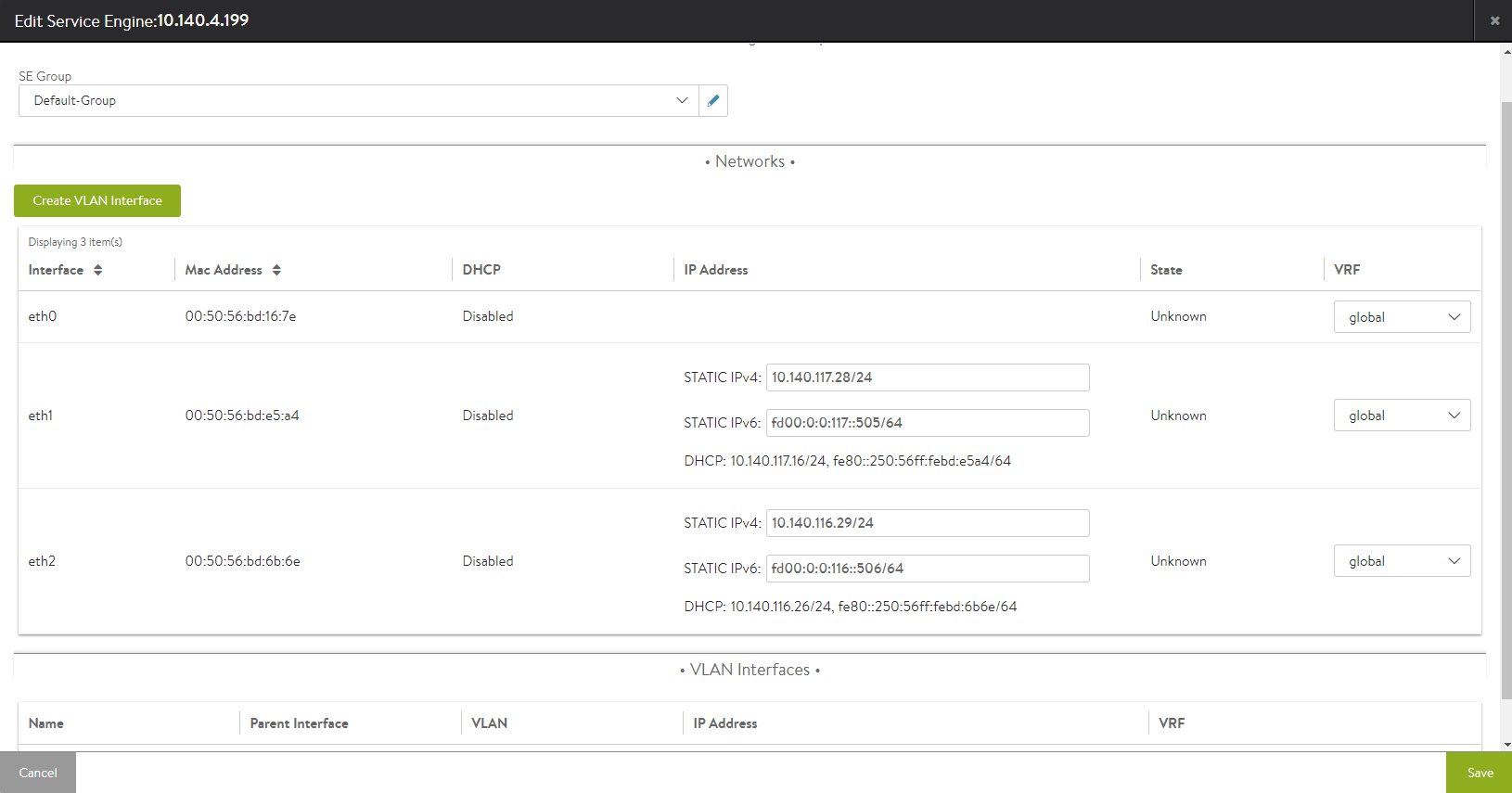
Click Create VLAN Interface.
Select the parent interface from the drop-down menu, and specify the VLAN and IP Address fields. Choose Global from the drop-down menu for VRF. Specify the IP prefix of the Service Engine’s data vNIC in the Static IP Prefix field. Click Save option.
The configured VLAN interface will be displayed in the VLAN Interfaces section of the Service Engine edit page.
Click Save to commit the change.
