Cisco ACI 2100 is a turn-key hosting operating system and hardware platform optimized for Data Center NFV. The platform facilitates the quick onboarding and lifecycle management of any Cisco or 3rd party VNF.
In this design option, the Avi Load Balancer will be deployed in No-orchestrator mode on Cisco ACI 2100, Avi Load Balancer SEs will be configured as BGP L3 Outs in APIC in order to exchange the virtual service routes, leaf/spine switches in ACI fabric will be learning this routes to forward the virtual service traffic to SE’s.
Logical Network Topology
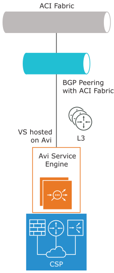
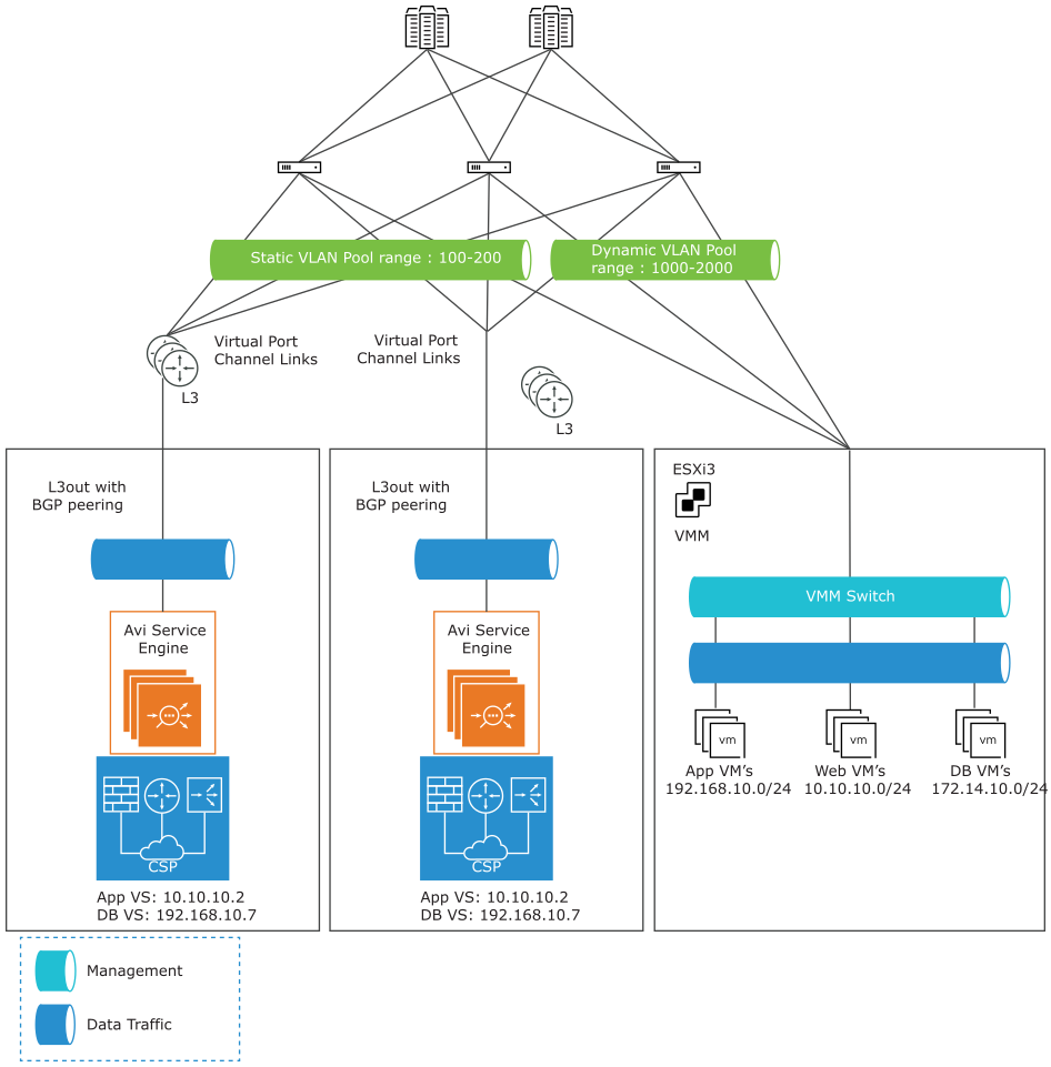
The logical view of one arm mode looks like the screenshot provided below, where Avi Load Balancer SE hosted on Cisco ACI 2100 will be connected to ACI Fabric as L3out using BGP peering. The clients are sourced from ACI fabric and can access the virtual service hosted on the SE.

The following is the logical network topology of the one arm mode design with BGP peering for SEs hosted on Cisco ACI 2100.

Logical Traffic Flow
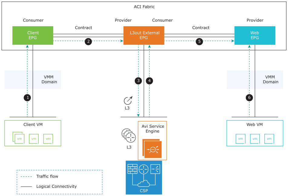
The traffic flow for client VM to access virtual service app hosted on the SE is shown as follows:
Client VM → ACI Fabric → Client EPG
Client EPG → Contract → L3out extern
L3out external EPG → ACI fabric → Avi SE
Avi SE → load balancing to back-end servers → ACI fabric → L3out external EPG
L3out external EPG → Contract → Web EPG
Web EPG → Web server VM

Service Engine Routing
Avi Load Balancer SEs can only publish the virtual service routes. It cannot learn any routes using BGP from any of the BGP peers. For few cases, SEs need to learn the routes from the BGP peer in order to send the return traffic to an appropriate next-hop which forwards the traffic. In such cases, you can use the auto gateway option to ensure that the return traffic is sent to the same MAC address from which it was received.
For detailed information, see Create a Virtual Service.
High Availability
As BGP is used for exchanging routes, high availability is entirely dependent on BGP. By default, the Service Engines are inactive/active state. For active/standby virtual service deployment, use the local preference option in ACI fabric. This allows you to choose one SE route as the most preferred one over other SEs.
For detailed information on local preference in ACI fabric, see L3 Config/Cisco APIC Layer 3 Configuration Guide.
References
In this deployment, Avi Load Balancer Controller works in No Orchestrator mode. Hence you need to manually install Service Engines. Customers can use Ansible in order to automate the installation.
For more details on Ansible Automation for Cisco CSP and Avi Load Balancer Deployment, see Ansible Role Avi Load Balancer Controller CSP.
The BGP peering and Virtual service configuration are same as mentioned in Network policy Mode with VMware No Access/Read Access.
For more details on Avi Load Balancer installation on Cisco CSP 2100, see Installing Avi Load Balancer for CSP 2100.
For more details on sizing guidelines, see Sizing Guidelines.
Before starting with Avi Load Balancer Deployment/Design hosted on Cisco CSP, for configuring Port Channel, to get maximum bandwidth on Service Engines, see Port Channel for CSP 2100 for more details.