


The topic explains the steps required to deploy the SE OVA.
In vCenter, click on File in the top menu and choose Deploy OVF Template.
Follow the Deploy OVA Template wizard instructions:
Choose Thick Provision Lazy Zeroed for disk format.
Choose the port groups for the Avi Load Balancer SE network connections. The Avi Load Balancer SE has ten vNICs. Connect the first vNIC to the management network. Connect the other vNICs to the respective data network.
For the management connection, choose a port group that will allow the Avi Load Balancer SEs to communicate with the Avi Load Balancer Controller. The Avi Load Balancer SE can be connected up to nine data networks. Choose a port group in the destination networks for each source network, where you can host the virtual services and pools. The Avi Load Balancer Controller expects the Avi Load Balancer SE’s data vNICs to be connected to virtual service and pool networks.
Specify the Avi Load Balancer Controller IP address.
Specify the Avi Load Balancer Controller’s authentication token key:
Log into Avi Load Balancer Controller.
Navigate to Infrastructure > Cloud. Click on the key icon to view the authentication token key.
Copy the authentication token.
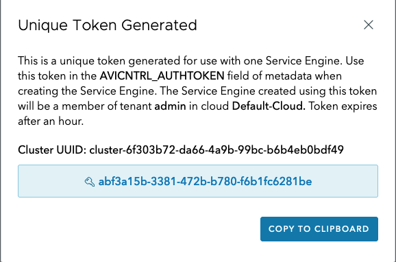
Paste the authentication token key into the Authentication Token for Avi field.
Specify the management IP address and default gateway. In the case of DHCP, leave this field empty.
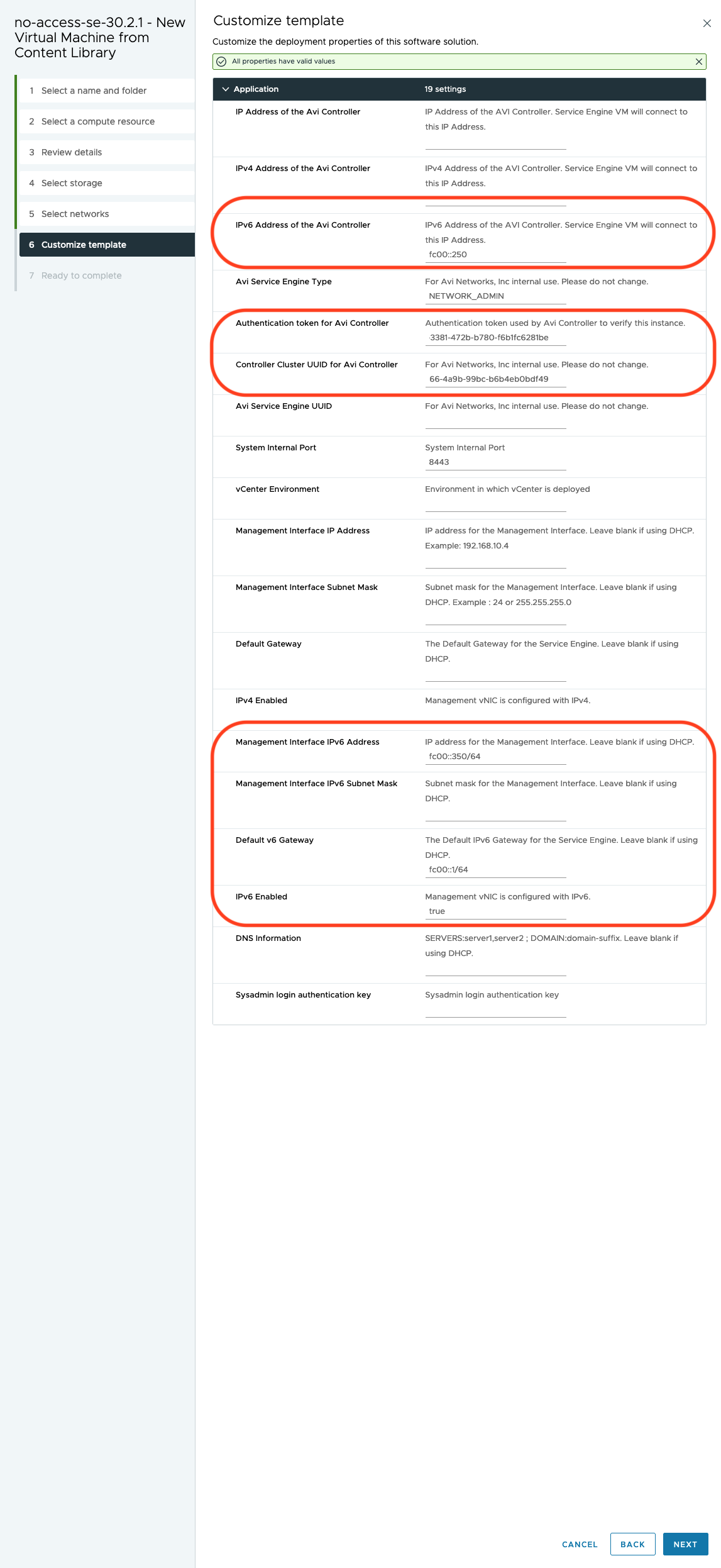
Avi Load Balancer supports IPv6 for management plane and communication between the Controller to Service Engine over IPv6. The following fields are added for IPv6 addresses in Service Engine OVF properties:
avi.mgmt-ip-v6.SE: Management interface IPv6 address.avi.mgmt-mask-v6.SE: Management interface IPv6 subnet mask.default-gw-v6.SE: The default IPv6 gateway for the Service Engine.mgmt_ip_v4_enable: To configure the SE management interface with a v4 IP, this field should be set to True. If this is False, the SE will not try to acquire an IPv4 address.mgmt_ip_v6_enable: To configure the SE management interface with a v6 IP, this field should be set to True. If this is False, the SE will not try to acquire an IPv6 address.If both
mgmt_ip_v4_enableandmgmt_ip_v6_enableare True, the SE will acquire both IPv4 and IPv6 addresses.
Specify IPv6 addresses in the aforementioned fields when the Service Engine connects to a Controller with IPv6 management IP for secondary interface with
SE_SECURE_CHANNELlabel set. The Service Engine management interface can be IPv4 or IPv6 or dual stack.Note:IP address of the Controller or AVICNTRL OVF field needs to be populated with IPv4 IP of the Controller in case of 30.1.x, 22.1.x, 21.1.x or earlier SE OVA deployments.
IPv4 address of the Controller or AVICNTRL4 OVF field needs to be populated with IPv4 IP of the Controller in case of 30.2.1 and later SE OVA deployments.
AVICNTRLV4: This field has to be populated if the Controller Secure Channel Interface IP is a v4 IP, otherwise the SE will not connect to the Controller.AVICNTRLV6: This field has to be populated if the Controller Secure Channel Interface IP is a v6 IP, otherwise the SE will not connect to the Controller.In case both are provided, SE uses
AVICNTRLV6to connect to the Controller.
In the VM properties menu, connect the Avi Load Balancer SE data vNICs that are required to reach a virtual service network and pool network to the port groups. Leave the unused vNICs disconnected.
For no orchestrator mode only, note the following information:
MAC address of the vNICs.
IP subnet of the port group.
This information will be used to identify the Avi Load Balancer SE interfaces, as the Controller does not have access to vCenter and hence cannot associate the Avi Load Balancer SE’s interface names with VMware’s interface names.
Power on the VM.
Depending on the Service Engine configuration, you will have to deploy additional SEs.
It is mandatory for No Orchestrator clouds on vCenter environments, that the AVISETYPE OVF parameter contains NETWORK_ADMIN,AVICLOUD_UUID:<cloud-uuid> if the write access cloud is also pointing to the same vCenter.
