Ensure that the following prerequisites are met before installing the Avi Load Balancer Controller:
Run CSP v2.3.1 at a minimum
Use VIRTIO as the disk type while configuring all Avi Load Balancer VNFs on CSP (Controllers and SEs)
i40evf bonds are supported only with CSP image version 2.4.1-185
CSP NIC Modes
Mode |
Description |
Comments |
Drivers and Supported NICs |
|---|---|---|---|
Access mode |
Traffic switched using OVS |
Allows physical NICs to be shared amongst VMs most generally. Performance is generally lower due to soft switch overhead. |
NA |
Passthrough mode |
Physical NIC directly mapped to VM |
Physical NIC is dedicated to a VM. With 1x10 Gbps pNIC per VM, a maximum of 2 VMs or 4 VMscan be created on a single CSP with 1 or 2 PCIe dual-port10-Gbps NIC cards. Provides the best performance. |
ixgbe driver supports these NICs: 82599, X520, X540, X550, X552 i40e driver supports these NICs: X710, XL710 |
SR-IOV mode |
Virtual network functionscreated from physical NIC |
Allows pNICs to be shared amongst VMs without sacrificing performance, as packets are switched in HW. Maximum 32 virtual functions (VFs) can be configured per pNIC. |
ixgbe-vf driver supports these NICs (and bonding): 82599, X520, X540, X550, X552 i40e-vf driver supports these NICs (and bonding): X710, XL710 |
Topology
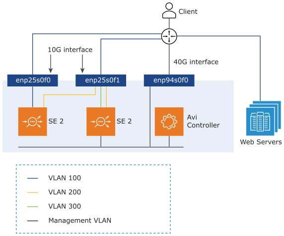
The SEs should be connected to pNICs of the CSP in passthrough (PCIe) or SR-IOV mode to leverage the DPDK capabilities of the physical NICs. For instance,
10 Gbps pNICs – enp25s0f0
40 Gbps pNICs – enp94s0f0
The SE can be connected to multiple VLANs on the pNICs’ virtual functions (VF) in SR-IOV mode. The management network can be connected to the 10-Gbps pNIC.

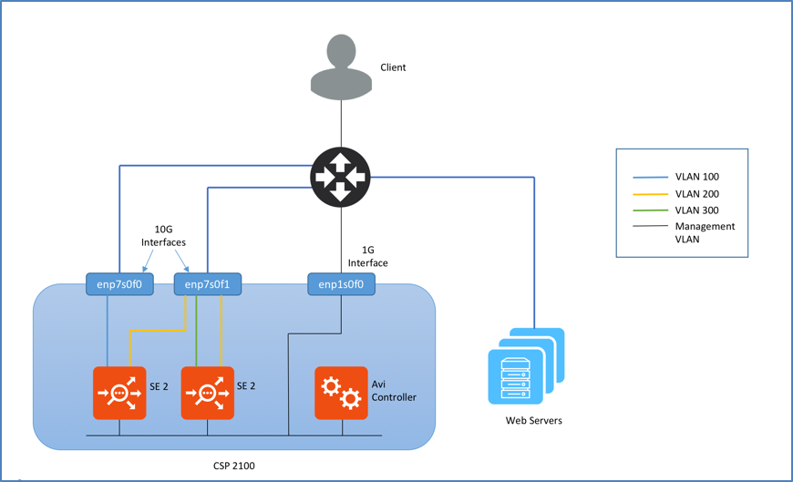
Topology of CSP 2100
The topology shown below consists of a Controller and Service Engines (SEs). To leverage the DPDK capabilities of the physical NICs, the SEs should be connected to the 10-Gbps enp7s0fx pNICs of the CSP 2100 in passthrough (PCIe) or SR-IOV mode. The SE can be connected to multiple VLANs on the pNICs’ virtual functions (VF) in SR-IOV mode. The management network can be connected to the 1-Gbps pNIC.

Numad Service
numad is a user-level daemon that provides placement advice and process management for efficient CPU and memory utilization. On CSP servers, numad runs every 15 seconds and scans all candidate processes for optimization. The following are the required criteria for a candidate:
RAM usage greater than 300 MB
CPU utilization greater than 50% of one core
On CSP, numad takes each candidate process (which includes VNFs) and attempts to move either the process or its memory, so that they are on the same NUMA node, i.e., a physical CPU and its directly-attached RAM. On CSP servers, as it fails to move pages from memory, it takes about 10 to 30 seconds to move memory between NUMA nodes. This causes the VNFs processed by numad to hang during that duration. All processes, which includes even the VNFs, will become a candidate for numad after the holddown timer expires.
The numad service will be disabled by default for CSP servers running versions 2.2.4 and above.
Disabling numad is safe and has no adverse effects.
Avi Load Balancer SEs have high background CPU utilization, even when passing no traffic. This makes the Avi Load Balancer SE VNF a candidate for numad, which hangs theAvi Load Balancer SE VNF. This leads to various issues such as:
Heartbeat failures
BGP peer flapping
Inconsistent performance
Disabling Numad Service
You can disable numad service as follows:
Install Cisco CSP software
Execute the following commands from CSP CLI:
avinet-3# config terminal
Entering configuration mode terminal
avinet-3(config)# cpupin enable
avinet-3(config)# end
Uncommitted changes found, commit them? [yes/no/CANCEL] yes
Commit complete.
avinet-3#
If the CSP server is running an older version than v2.2.4, contact Cisco support to disable numad.