


Virtual LAN (VLAN)-backed logical segments are created in a VLAN transport zone, and are managed by the Avi Load Balancer. Most of the large brownfield deployments use VLAN-backed segments for configuring VLAN micro-segmentation with Avi Load Balancer, since it is simple and non-disruptive to the existing environment.
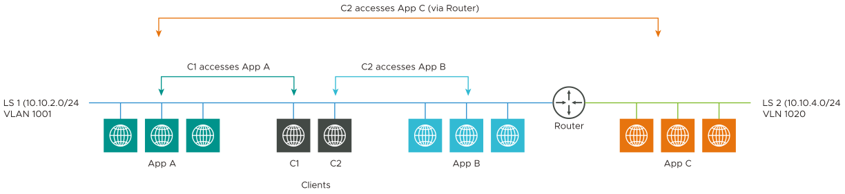
As shown in the below image, micro-segmentation rules can be configured so that:
Client C1 can only access App A.
Client C2 can only access App B or App C.
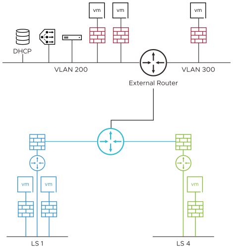
There are different VLAN segments deployment models using which this configuration can be achieved:
Single VLAN-TZ and N-VDS.
Multiple VLAN-TZ on different N-VDS.
Overlay-TZ and VLAN-TZ on single N-VDS.
Overlay-TZ and VLAN-TZ on different N-VDS.
One of the typical deployments is Overlay-TZ and VLAN-TZ on different NSX-T Virtual Distributed Switch (N-VDS).
This is used for shared or isolated physical switching or routing infra, PCI or DMZ scenarios.
NSX ALB Integration for VLAN Segments
The VLAN segments deployment scenario is similar to a vCenter cloud where the definition of the network segment (VIP and Mgmt) comes from NSX (within the respective TZ).
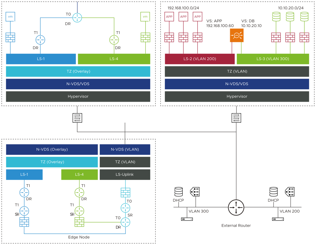
The logical representation of NSX ALB integration for VLAN segments is explained below:
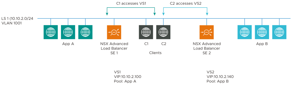
Virtual service placements on the Avi Load Balancer SEs are:
SE |
Virtual Service |
VIP |
Pool |
|---|---|---|---|
Avi SE1 |
VS1 |
10.10.2.100 |
App A |
Avi SE2 |
VS2 |
10.10.2.140 |
App B |
The virtual services VS1 and VS2 belong to the same IP Subnet. So the data vNICs of SE1 and SE2 are connected to the same VLAN Logical Segment LS1 (VLAN 1001).
There are different deployment modes for NSX ALB integration for VLAN Segments:
SE Placement(SE-Management Network) |
VIP Placement(SE-Data Network) |
Supported in NSX ALB Version |
|---|---|---|
Overlay |
Overlay |
20.1.1 |
VLAN |
Overlay |
20.1.5 |
VLAN |
VLAN |
20.1.6 |
Overlay |
VLAN |
20.1.7 |
VLAN-Backed Segments for Service Engine Management Network
Consider that an Avi Load Balancer Controller is deployed, and a virtual service has to be created.
In the cloud connector configuration,
LS-4 (VLAN) segment is selected as SE Management Network.
LS-3 (Overlay) segment is selected as VIP/Data Network.
There is no change in the traffic flow.
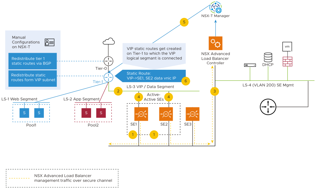
Service Engines are created based on the HA.
In this example, active-active SEs are considered, and this will spin up two SEs.
For these service engines, this is the overlay where the data NIC will be created.
The VLAN logical segment, is independent of Tier-1 or Tier-0.
The Avi Load Balancer Controller will communicate with the SEs on this VLAN logical segment and verify if the SEs are coming up. After the SEs are up, it attaches the Data NIC as overlay.
The route is created on Tier-1.
For the VIP, SE 1 and SE 2 are the next hop.
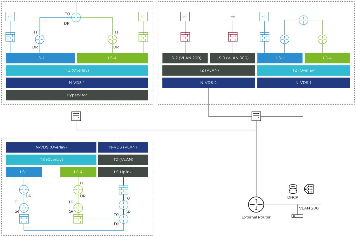
VLAN-Backed Segments for Service Engine Data Network
Consider that an Avi Load Balancer Controller is deployed, and a virtual service has to be created.
In the NSX-T cloud connector configuration:
LS-3 (VLAN 200) Segment is selected as SE Management Network.
LS-4 (VLAN 300) Segment is selected as VIP/Data Network.
The implementation of VLAN-Backed Data segment is as shown below:
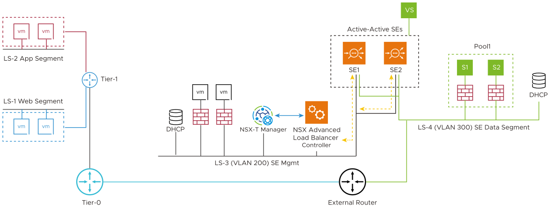
The virtual service is created with VIP in LS-4 VLAN segment (VLAN-300) with explicit placement subnet configured as LS-4 VLAN segment’s network and subnet. While creating the pool, user selects the pool placement subnet as LS-4 VLAN segment’s network and subnet.
SEs will be created based on the HA mode. In this example, active-active SEs are considered, with min-scale as two for two SEs to spin up.
SEs Management NIC will be created in LS-3 VLAN segment (VLAN-200) and will communicate with controller.
Once the SEs boots up completely, the Avi Load Balancer Controller will attach the data NIC from LS-4 VLAN segment (VLAN-300).
In NSX-T VLAN backed segments, the Placement Network details are not auto discovered. The details have to be manually selected.
Configuring the NSX-T Cloud
In NSX ALB, the NSX-T Cloud is configured to select the VLAN Transport Zone, and VLAN Segment for management interface of SE as explained below:
From the Avi Load Balancer UI, navigate to .
Click or edit an existing cloud.
Under Management Network, select the VLAN Transport Zone where the SE will be placed.
Select the management VLAN Segment where SE management NIC will get the IP.
Under Data Networks select the data Transport Zone for the SEs.
Select the data VLAN Segments path to use for the SEs.
Complete the cloud configuration and click Save.
In this example, an existing NSX-T cloud is edited.
Setting up the VLAN Backed Segment Networks for VIP and SE Data Segments
Once the NSX-T cloud is configured with the respective VLAN segments for the management and data networks, the segments are populated based on the cloud configuration.
To view the segments:
Navigate to and select the cloud.
The segments are displayed.
The segments support both IPv4 and IPv6.
Click on a segment to expand it.
Click on the edit icon to view the Edit Network Settings screen.
To use these VIP VLAN segments with auto allocation of IP addresses, configure the IPAM profile and attach it to the NSX-T cloud as shown below:
Navigate to .
Click Create.
Select IPAM.
Enter the Name and select the Type as Avi Vantage IPAM.
Select the required cloud.
Click on Add Usable Network and update all the segments created.
Click Save.
The created IPAM profile is populated in the Edit Cloud screen for the particular cloud under the IPAM/DNS section. Select the IPAM to attach it to the cloud.
Configuring Virtual Services
To configure a virtual service:
Navigate to .
Click the edit icon for the required virtual service.
Under VIP Address, select the Auto Allocate check box.
Configure the VIP Address allocation details.
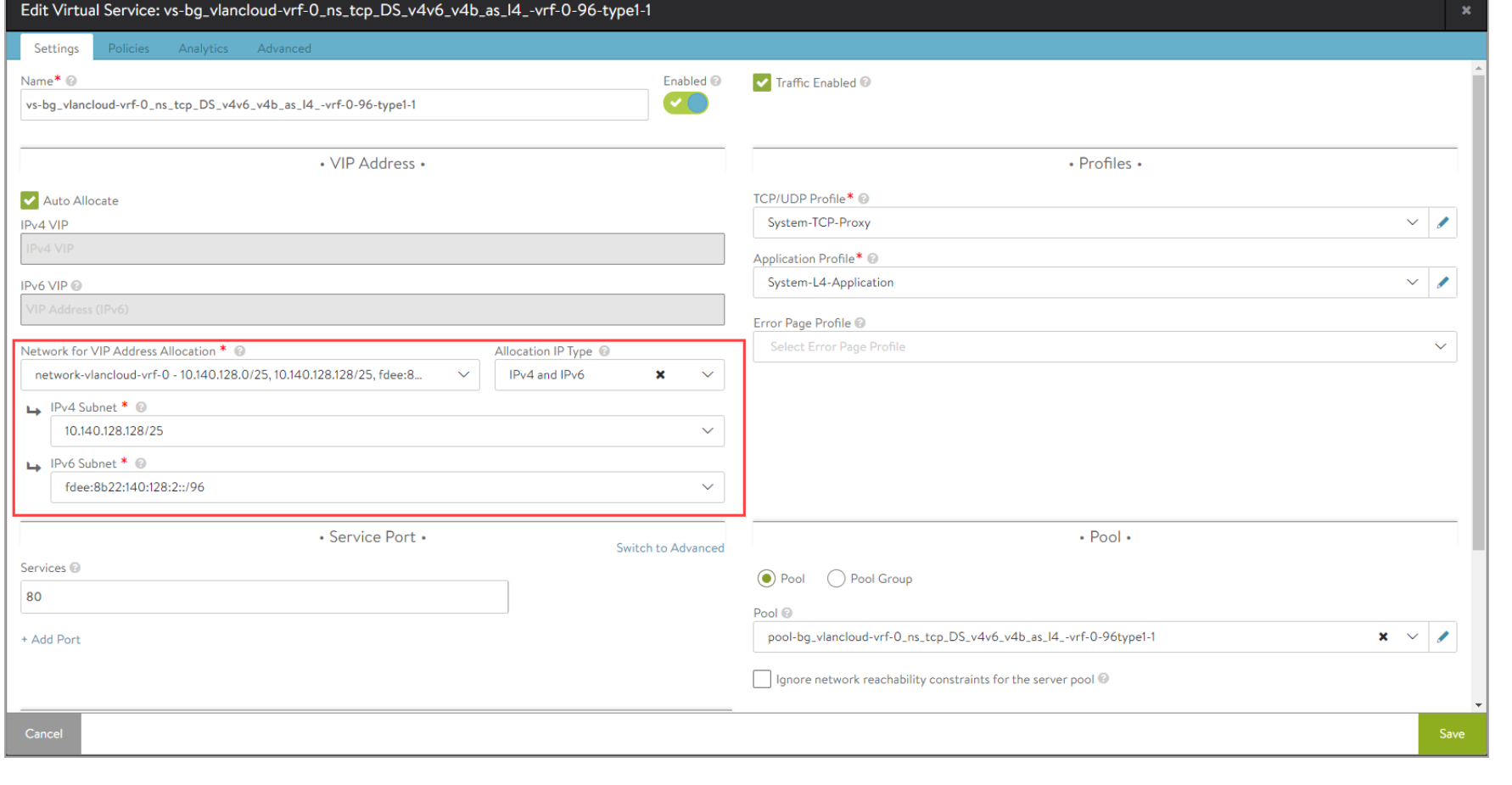
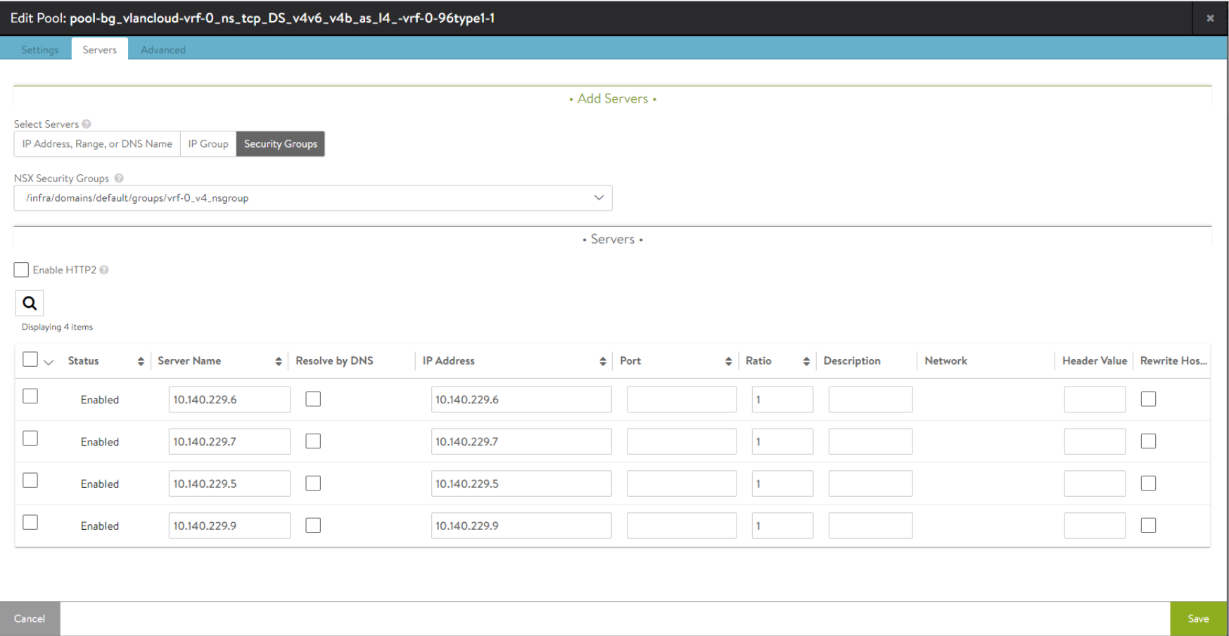
To configure the pool, click on the edit icon under the Pool section.
Under the Servers tab, select Security Groups and add servers.
Starting with NSX Advanced Load Balancer 21.1.3, the option to configure placement network is available under the VS VIP setting. Navigate to Applications > VS VIPs, select the specific VS VIP, and click on edit. Select the VIP and click on the edit icon to add the placement network.
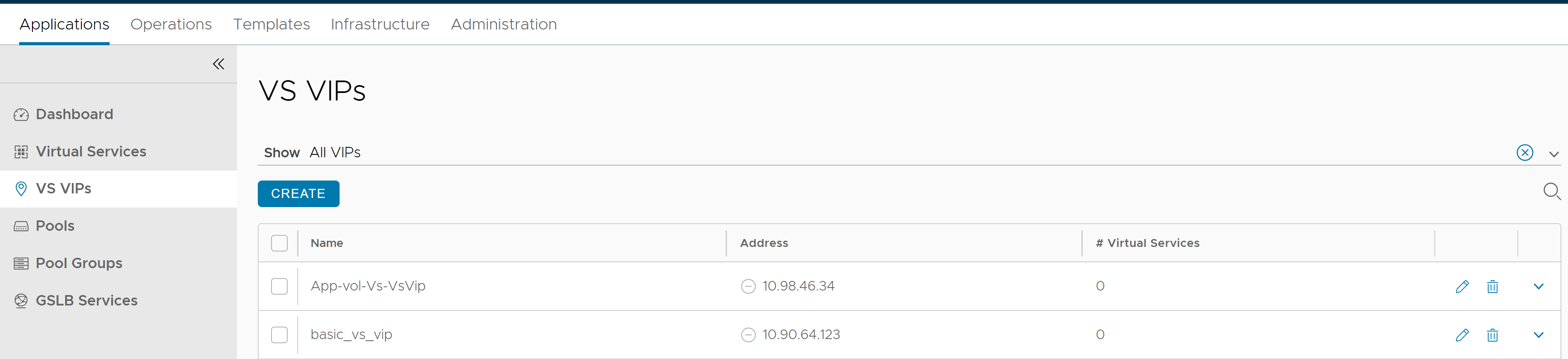
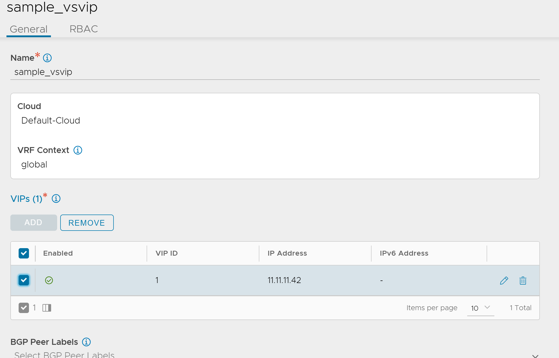
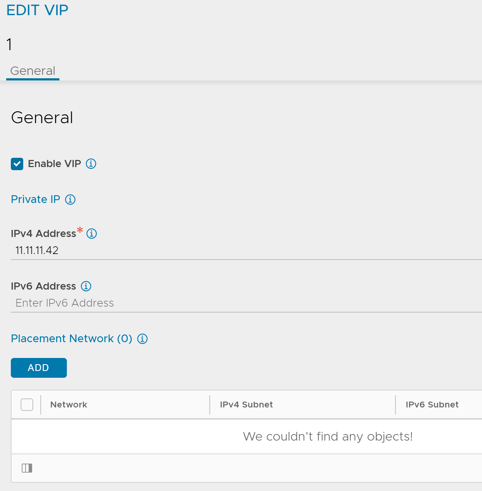
Note:In NSX-T VLAN backed segments, the Placement Network details are not auto discovered. The details have to be manually selected.
Click Save.
In NSX-T VLAN backed segments, the Placement Network details are not auto discovered. The details have to be manually selected.
Transport zone cannot be changed once the cloud is created.
