A Carbon Black EDR cluster must operate with multiple servers in the same way as a standalone instance. As a result, each role must be responsible for certain aspects of a Carbon Black EDR instance.
The primary node contains the user interface and is the primary front end for the API and most integrations. As users navigate the web console, standard API endpoint calls are made to the primary, which in turn queries the appropriate back-end storage location. When process data is queried, the primary distributes the query to the minions and renders the aggregated results. However, if a binary, threat intel, or alert search is performed, it only queries its local Solr cores.
The primary also contains the only instance of the PostgreSQL database that houses most of the application-specific configuration and certain state information that is used for sensor management. The primary is in charge of managing the sensor configuration and communications, which include the Live Response capabilities. Managing sensors not only requires sensor state information, but requires minion state metrics to independently distribute minion bandwidth. This allows its assigned sensors to submit data.
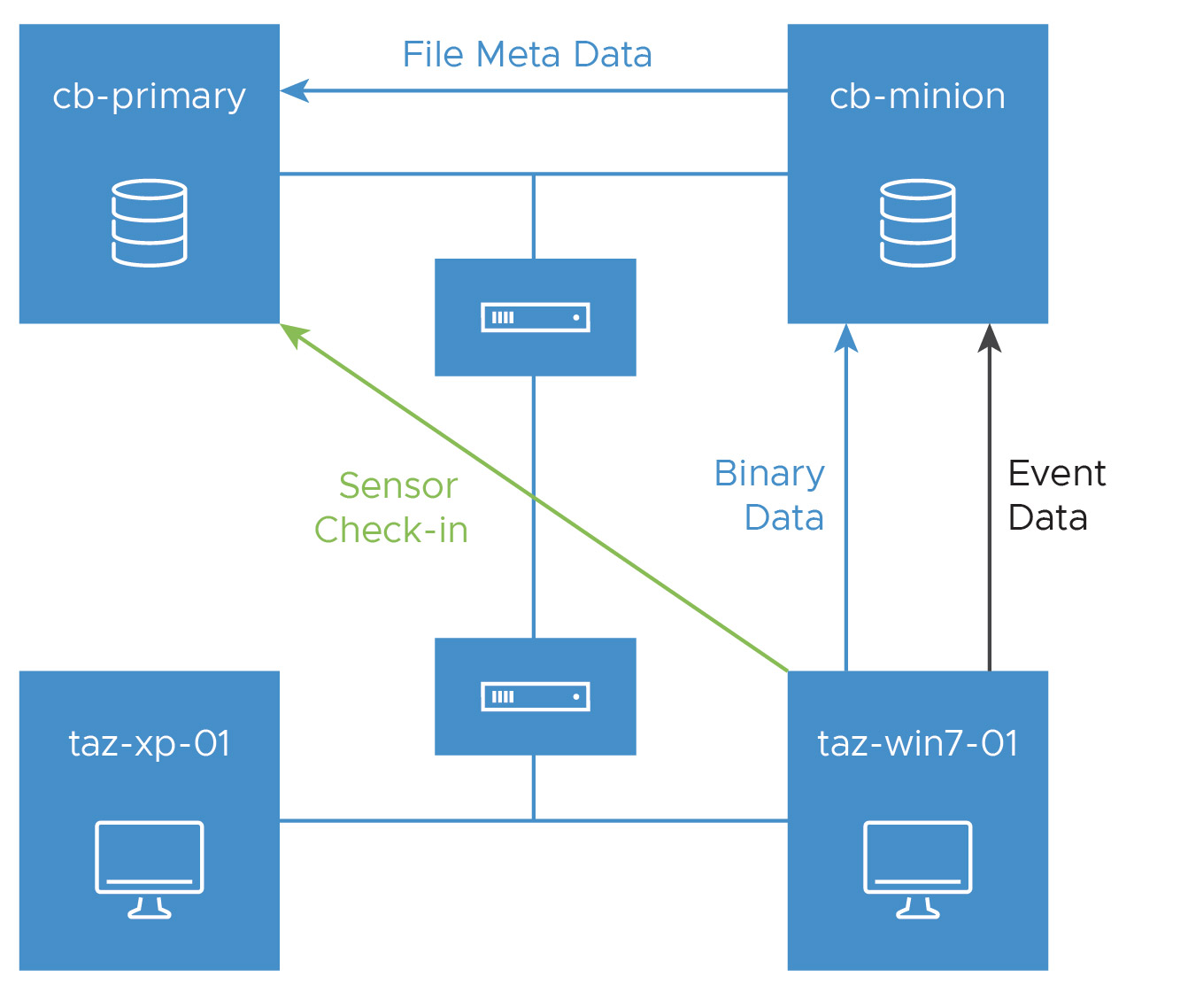
The minions serve as the main ingestion point for sensor data. When the primary instructs a sensor to send data to the minion, the minion receives the data and begins to ingest the data for storage. A minion will store all process-related data in its cbevents Solr core(s), where it manages its indexes separately from the rest of the cluster. This data is retrieved when the primary initiates a distributed query. Binary data is forwarded to the primary node for storage and management. This is done only one time per unique binary per sensor. Unlike the binary metadata, copies of the binaries are stored locally on the minion. The copies are submitted and stored only one time per Carbon Black EDR cluster or instance. The distribution of the binary storage depends on the sensor to which that binary was submitted. This data flow is illustrated in the following figure: