


As part of the overlay design, you determine the NSX-T Data Center configuration for handling traffic between management workloads in VMware Cloud Foundation. You determine the configuration of the vSphere Distributed Switch for the default management cluster and the NSX segments on it, and of the transport zones.
This conceptual design provides the network virtualization design of the logical components that handle the data to and from management workloads in the environment. For an environment with multiple VMware Cloud Foundation instances, you replicate the design of the first VMware Cloud Foundation instance to the additional VMware Cloud Foundation instances.
ESXi Host Transport Nodes
A transport node in NSX-T Data Center is a node that is capable of participating in an NSX data plane. The management domain contains multiple ESXi hosts in a vSphere cluster to support management workloads. You register these ESXi hosts as transport nodes so that networks and workloads on that host can use the capabilities of NSX-T Data Center. During the preparation process, the native vSphere Distributed Switch for the management domain is extended with NSX-T Data Center capabilities.
| Decision ID |
Design Decision |
Design Justification |
Design Implication |
|---|---|---|---|
| VCF-MGMT-NSX-SDN-025 |
Enable all ESXi hosts in the management domain as transport nodes in NSX-T Data Center. |
Enables distributed routing, logical segments, and distributed firewall. |
None. |
| VCF-MGMT-NSX-SDN-026 |
Configure each ESXi host as a transport node without using transport node profiles. |
Enables the participation of ESXi hosts and the virtual machines on them in NSX overlay and VLAN networks. Transport node profiles can only be applied at the cluster level. Because in an environment with multiple availability zones each availability zone is connected to a different set of VLANs, you cannot use a transport node profile. |
You must configure each transport node with an uplink profile individually. |
Host TEP IP Assignment
A host TEP (tunnel end-point) interface is created for each uplink on the allocated distributed switch. This TEP interface is used for data plane communication between transport nodes. The IP address for the TEP interface can be statically assigned by using SDDC Manager or dynamically assigned over DHCP.
IP Assignment Method |
Process |
Advantages |
Disadvantages |
|---|---|---|---|
DHCP by using a DHCP server in the data center |
A DHCP scope with a pool of available IP addresses, gateway, and subnet information for each overlay VLAN is configured in a DHCP server. Newly-configured hosts require a DHCP address on the overlay VLAN. |
|
|
Static by using SDDC Manager |
A group or pool of available IP addresses, gateway, and subnet information for each overlay VLAN is provided to SDDC Manager. Newly-configured hosts are allocated one or more addresses from that pool during the initial host configuration. |
|
|
| Decision ID | Design Decision |
Design Justification |
Design Implication |
|---|---|---|---|
| VCF-WLD-NSX-SDN-027 | Use DHCP to assign IP addresses to the host TEP interfaces. |
Required for deployments where a cluster spans Layer 3 network domains such as multiple availability zones and management clusters that span Layer 3 domains. |
DHCP server is required for the host overlay VLANs. |
Virtual Switches
NSX segments are logically abstracted segments to which you can connect management workloads. A single segment is mapped to a unique Geneve segment that is distributed across the ESXi hosts in the transport zone when the connected workloads are powered on these hosts. The segment supports line-rate switching in the ESXi host without the constraints of VLAN sprawl or spanning tree issues.
Distributed switches are manageable only when the vCenter Server instance is available. You can consider vCenter Server a Tier-1 application.
Distributed switches with NSX-T Data Center capabilities are manageable only when the vCenter Server instance and NSX Manager cluster is available. You can consider vCenter Server and NSX Manager as Tier-1 applications.
N-VDS instances are manageable only when the NSX Manager cluster is available. You can consider the NSX Manager cluster as a Tier-1 application.
| Decision ID |
Design Decision |
Design Justification |
Design Implication |
|---|---|---|---|
| VCF-MGMT-NSX-SDN-028 |
Use the vSphere Distributed Switch for the default cluster in the management domain that is enabled for NSX-T Data Center. |
To use features such as distributed routing, management workloads must be connected to NSX segments. |
Management occurs jointly from the vSphere Client to NSX Manager. However, you must perform all network monitoring in the NSX Manager user interface or another solution. |
Configuration of the vSphere Distributed Switch with NSX-T Data Center
The default cluster in the management domain uses a single vSphere Distributed Switch with a configuration for system traffic types, NIC teaming, and MTU size. See vSphere Networking Design for the Management Domain.
VMware Cloud Foundation supports one distributed switch with NSX per cluster. Custom distributed switches are not supported.
To support uplink and overlay traffic for the NSX Edge nodes for the management domain, you must create several port groups on the vSphere Distributed Switch for the management domain. The VMkernel adapter for the host TEP is connected to the host overlay VLAN, but does not require a dedicated port group on the distributed switch. The VMkernel network adapter for host TEP is automatically created when you configure the ESXi host as a transport node.
Connect the NSX Edge appliances and the VMkernel adapter for the host overlay traffic to different VLANs and subnets. The VLAN IDs for the NSX Edge nodes are mapped to the VLAN trunk port groups for the edge uplinks on the host.
Function |
Number of Physical NIC Ports |
Teaming Policy |
MTU |
|---|---|---|---|
|
2 |
|
9000 |
vmnic |
Function |
Connected to |
|---|---|---|
0 |
Uplink |
Top of rack switch 1 |
1 |
Uplink |
Top of rack switch 2 |
Segment Name |
Type |
Purpose |
|---|---|---|
Management - first availability zone |
VLAN |
Management traffic |
vMotion - first availability zone |
VLAN |
vSphere vMotion traffic |
vSAN - first availability zone |
VLAN |
vSAN traffic |
Edge Uplink 1 |
VLAN Trunk |
Edge node overlay and uplink traffic to the first top of rack switch |
Edge Uplink 2 |
VLAN Trunk |
Edge node overlay and uplink traffic to the second top of rack switch |
NFS storage - first availability zone |
VLAN |
NFS traffic |
auto created (Host TEP) |
- |
Host overlay |
|
auto created (Host TEP)
|
- |
Host overlay |
auto created (Hyperbus) |
- |
- |
In a deployment that has multiple availability zones, you must provide new or extend the existing networks.
Segment Name |
Type |
Availability Zone |
Purpose |
|---|---|---|---|
Management - second availability zone |
VLAN |
Second availability zone |
Management traffic in the second availability zone |
vMotion - second availability zone |
VLAN |
Second availability zone |
vSphere vMotion traffic in the second availability zone |
vSAN - second availability zone |
VLAN |
Second availability zone |
vSAN traffic in the second availability zone |
Edge Uplink 1 |
VLAN Trunk |
Stretched between both availability zones |
Edge node overlay and uplink traffic to the first top of rack switch in the second availability zone |
Edge Uplink 2 |
VLAN Trunk |
Stretched between both availability zones |
Edge node overlay and uplink to the second top of rack switch in the second availability zone |
NFS storage - second availability zone |
VLAN |
Second availability zone |
- |
auto created (Host TEP) |
- |
- |
Host overlay |
auto created (Host TEP) |
- |
- |
Host overlay |
auto created (Hyperbus) |
- |
- |
- |
Virtual Segments
Geneve provides the overlay capability to create isolated, multi-tenant broadcast domains in NSX-T Data Center across data center fabrics, and enables customers to create elastic, logical networks that span physical network boundaries, and physical locations.
The first step in creating these logical networks is to isolate and pool the networking resources. By using the Geneve overlay, NSX-T Data Center isolates the network into a pool of capacity and separates the consumption of these services from the underlying physical infrastructure. This model is similar to the model vSphere uses to abstract compute capacity from the server hardware to create virtual pools of resources that can be consumed as a service. You can then organize the pool of network capacity in logical networks that are directly attached to specific applications.
In the vSphere architecture, the encapsulation is performed at the TEP VMkernel adapter of the ESXi host and before being sent on the physical network, making the Geneve overlay transparent to both the guest virtual machines and the underlying Layer 3 network. The Tier-0 gateway provides gateway services between overlay and non-overlay hosts, for example, a physical server or the Internet router. The NSX Edge node translates overlay segment IDs to VLAN IDs, so that non-overlay hosts can communicate with virtual machines on an overlay network.
| Decision ID |
Design Decision |
Design Justification |
Design Implication |
|---|---|---|---|
| VCF-MGMT-NSX-SDN-029 |
To provide virtualized network capabilities to management workloads, use overlay networks with NSX Edge nodes and distributed routing. |
|
Requires configuring transport networks with an MTU size of at least 1,600 bytes. |
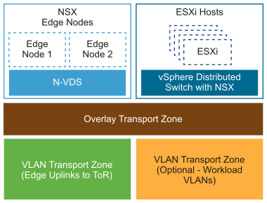
Transport Zones
| Decision ID |
Design Decision |
Design Implication |
Design Justification |
|---|---|---|---|
| VCF-MGMT-NSX-SDN-030 |
Create a single overlay transport zone for all overlay traffic across the management domain and NSX Edge nodes. |
|
None. |
| VCF-MGMT-NSX-SDN-031 |
Create a single VLAN transport zone for uplink VLAN traffic that is applied only to NSX Edge nodes. |
Ensures that uplink VLAN segments are configured on the NSX Edge transport nodes. |
If VLAN segments are needed on hosts, you must create another VLAN transport zone for the host transport nodes only. |
Uplink Policy for ESXi Host Transport Nodes
Uplink profiles define policies for the links from ESXi hosts to NSX segments or from NSX Edge appliances to top of rack switches. By using uplink profiles, you can apply consistent configuration of capabilities for network adapters across multiple ESXi hosts or NSX Edge nodes.
Uplink profiles can use either load balance source or failover order teaming. If using load balance source, multiple uplinks can be active. If using failover order, only a single uplink can be active.
| Decision ID |
Design Decision |
Decision Justification |
Decision Implication |
|---|---|---|---|
| VCF-MGMT-NSX-SDN-032 |
Create an uplink profile with a load balance source teaming policy with two active uplinks for ESXi hosts. |
For increased resiliency and performance, supports the concurrent use of both physical NICs on the ESXi hosts that are configured as transport nodes. |
None. |
Replication Mode of Segments
The control plane decouples NSX-T Data Center from the physical network. The control plane handles the broadcast, unknown unicast, and multicast (BUM) traffic in the virtual segments.
The following options are available for BUM replication on segments.
BUM Replication Mode |
Description |
|---|---|
Hierarchical Two-Tier |
The ESXi host transport nodes are grouped according to their TEP IP subnet. One ESXi host in each subnet is responsible for replication to an ESXi host in another subnet. The receiving ESXi host replicates the traffic to the ESXi hosts in its local subnet. The source ESXi host transport node knows about the groups based on information it has received from the control plane. The system can select an arbitrary ESXi host transport node as the mediator for the source subnet if the remote mediator ESXi host node is available. |
Head-End |
The ESXi host transport node at the origin of the frame to be flooded on a segment sends a copy to every other ESXi host transport node that is connected to this segment. |
| Decision ID |
Design Decision |
Design Justification |
Design Implications |
|---|---|---|---|
| VCF-MGMT-NSX-SDN-033 |
Use hierarchical two-tier replication on all overlay segments. |
Hierarchical two-tier replication is more efficient because it reduced the number of ESXi hosts the source ESXi host must replicate traffic to. |
None. |
