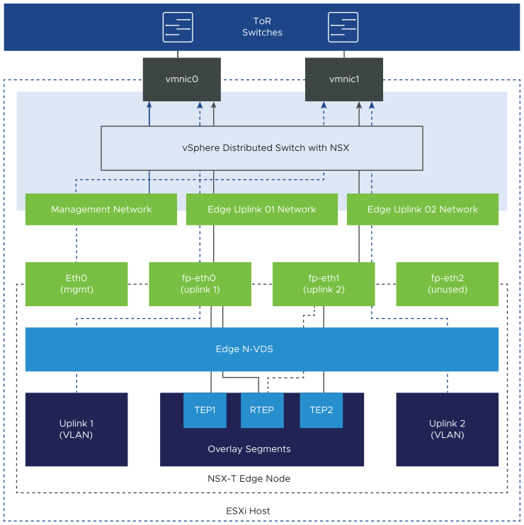
In each VMware Cloud Foundation instance, you implement an NSX Edge configuration with a single N-VDS. You connect the uplink network interfaces of the edge appliance to VLAN trunk port groups that are connected to particular physical NICs on the host.
The NSX Edge node contains a virtual switch, called an N-VDS, that is managed by NSX-T Data Center. This internal N-VDS is used to define traffic flow through the interfaces of the edge node. An N-VDS can be connected to one or more interfaces. Interfaces cannot be shared between N-VDS instances.
If you plan to deploy multiple VMware Cloud Foundation instances, apply the same network design to the NSX Edge cluster in the second and other additional VMware Cloud Foundation instances.

Decision ID |
Design Decision |
Design Justification |
Design Implication |
|---|---|---|---|
VCF-WLD-NSX-EDGE-NET-001 |
Connect the management interface |
Provides connection to the NSX Manager cluster. |
None. |
VCF-WLD-NSX-EDGE-NET-002 |
|
Because VLAN trunk port groups pass traffic for all VLANs, VLAN tagging can occur in the NSX Edge node itself for easy post-deployment configuration.
|
None. |
VCF-WLD-NSX-EDGE-NET-003 |
Use a single N-VDS in the NSX Edge nodes. |
|
None. |
VCF-WLD-NSX-EDGE-NET-004 |
Use a dedicated VLAN for the edge overlay network that is segmented from the host overlay VLAN. |
The edge overlay network must be isolated from the host overlay network to protect the host overlay traffic from edge-generated overlay traffic. |
|
For a multi-region SDDC, an RTEP VLAN is needed for overlay traffic between regions.
Decision ID |
Design Decision |
Design Justification |
Design Implication |
|---|---|---|---|
VCF-WLD-NSX-EDGE-NET-005 |
Allocate a separate VLAN for edge RTEP overlay that is different from the edge overlay VLAN. |
|
You must allocate another VLAN in the data center infrastructure for edge RTEP overlay. |