


Design the routing configuration in NSX-T Data Center for multiple VMware Cloud Foundation instances to support network span for customer applications that require resilient connectivity at multiple locations and to enable granular control on traffic from and to each instance.
North-South Routing
In a routing design for an environment with multiple VMware Cloud Foundation instances, you identify the VMware Cloud Foundation instances that an SDN network must span and whose physical location must let ingress and egress traffic.
Network traffic that is entering or leaving the SDN networks with a preference to the physical location of VMware Cloud Foundation instance and failover is a key design choice for a multi-site deployment. This design does not use local egress, that is, traffic leaving and entering any location which the network spans. Instead, this design uses a preferred and failover VMware Cloud Foundation instance for all networks. The complexity of local egress that is, controlling local ingress to prevent asymmetrical routing, is not necessary for this design.
In this design, an NSX component can be primary for one or more VMware Cloud Foundation instances. During a failure at the location of a VMware Cloud Foundation instance, you must set a network component as primary in another VMware Cloud Foundation instance manually.
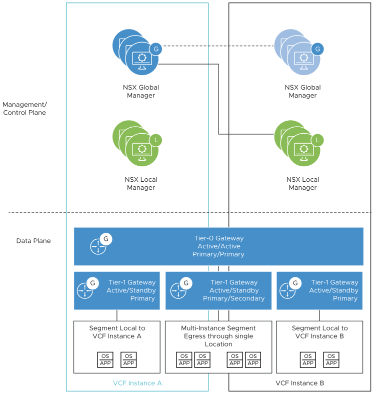
Tier-0 Gateways
In NSX-T Federation, a Tier-0 gateway can span multiple VMware Cloud Foundation instances. Each instance contains a logical unit of the Tier-0 gateway which is assigned to the edge cluster in that instance and is configured to interface with the data center top of rack switches in the data center.
Each VMware Cloud Foundation instance that is in the scope of a Tier-0 gateway can be configured as primary or secondary. A primary instance passes traffic for any other SDN service such as Tier-0 logical segments or Tier-1 gateways. A secondary instance routes traffic locally but does not egress traffic outside the SDN or advertise networks in the data center.
When deploying an additional VMware Cloud Foundation instance, the Tier-0 gateway in the first instance is extended to the new instance.
In this design, the Tier-0 gateway in each VMware Cloud Foundation is configured as primary. Although the Tier-0 gateway technically supports local-egress, the design does not recommend the use of local egress. Ingress and egress traffic is controlled at the Tier-1 gateway level.
Decision ID |
Design Decision |
Design Justification |
Design Implication |
|---|---|---|---|
VCF-WLD-NSX-SDN-FED-001 |
Extend the VI workload domain active-active Tier-0 gateway to the second VMware Cloud Foundation instance. |
|
Active-active Tier-0 gateways cannot provide stateful services such as NAT. |
VCF-WLD-NSX-SDN-FED-002 |
Set the Tier-0 gateway as primary for all VMware Cloud Foundation instances. |
|
None. |
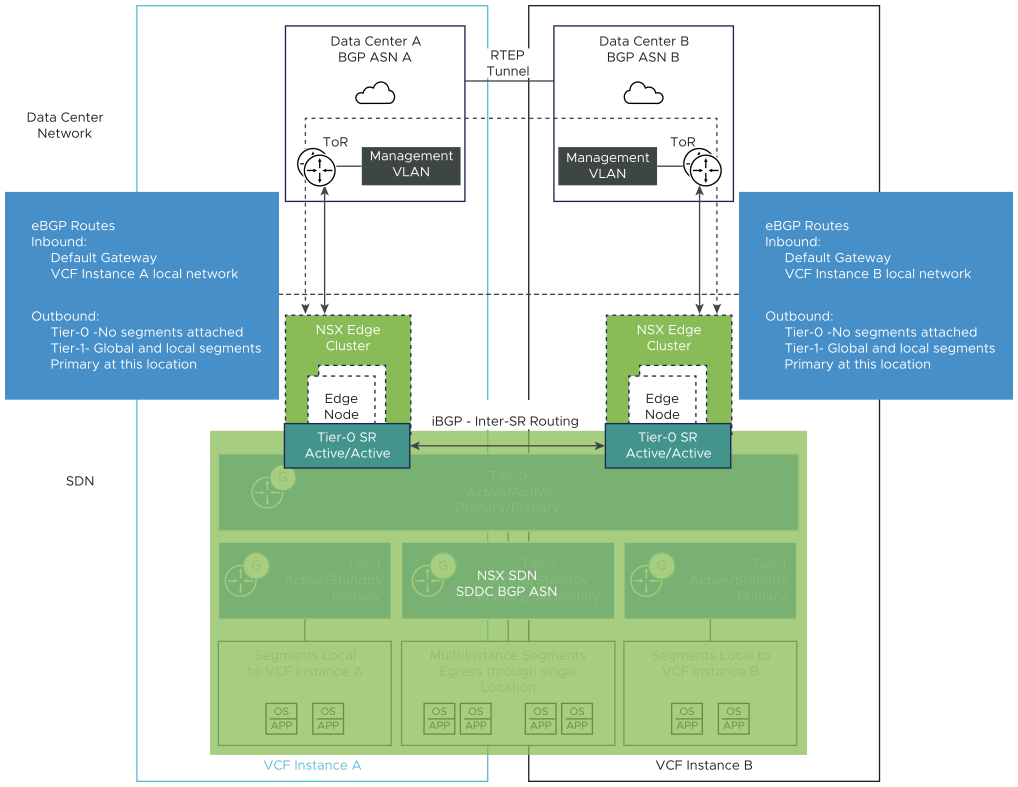
Each VMware Cloud Foundation instance has its own NSX Edge cluster with associated uplink VLANs for north-south traffic flow for that data center. Each Tier-0 gateway unit peers with the top of rack switches over eBGP.
Decision ID |
Design Decision |
Design Justification |
Design Implication |
|---|---|---|---|
VCF-WLD-NSX-SDN-FED-003 |
From the global Tier-0 gateway, establish BGP neighbor peering to the ToR switches connected to the second VMware Cloud Foundation instances. |
|
None. |
Tier-1 Gateways
A Tier-1 gateway can span several VMware Cloud Foundation instances. As with a Tier-0 gateway, you can configure an instance's location as primary or secondary for a Tier-1 gateway. The gateway passes ingress and egress traffic for the logical segments connected to it.
Any logical segments connected to the Tier-1 gateway follow the span of the Tier-1 gateway. If the Tier-1 gateway spans several VMware Cloud Foundation instances, any segments connected to that gateway become available in both instances.
Using a Tier-1 gateway enables more granular control on logical segments in the first and second VMware Cloud Foundation instances. Design the configuration of the Tier-1 gateway that is specific to a VMware Cloud Foundation instance and to cross-instance communication in the VI workload domain according to the requirements of the customer workloads.
A Tier-1 gateway advertises its networks to the connected local-instance unit of the Tier-0 gateway. In the case of primary-secondary location configuration, the Tier-1 gateway advertises its networks only to the Tier-0 gateway unit in the instance's location where the Tier-1 gateway is primary. The Tier-0 gateway unit then re-advertises those networks to the data center in the sites where that Tier-1 gateway is primary. During failover of the components in the first VMware Cloud Foundation instance, the IT administrator must manually set the Tier-1 gateway in the second VMware Cloud Foundation instance as primary. Then, networks become advertised through the Tier-1 gateway unit in the second instance.
