


Design of the physical data center network includes defining the network topology for connecting the physical switches and the ESXi hosts, determining switch port settings for VLANs and link aggregation, and designing routing.
A software-defined network (SDN) both integrates with and uses components of the physical data center. SDN integrates with your physical network to support east-west transit in the data center and north-south transit to and from the SDDC networks.
Several typical data center network deployment topologies exist:
Core-Aggregation-Access
Leaf-Spine
Hardware SDN
This design uses the leaf-spine network topology, because in a single data center deployment, it provides predictable performance, scalable nature, and applicability across multiple vendors. Other data center network topologies, such as core-aggregation-access, are also supported.
In an environment with multiple availability zones, Layer 2 networks must be stretched between the availability zones by the physical infrastructure. You must also provide a Layer 3 gateway that is highly available between the availability zones. The method for stretching these Layer 2 networks and providing a highly available Layer 3 gateway is vendor-specific.
In an environment with multiple availability zones or VMware Cloud Foundation Instances, dynamic routing is needed to provide networks with the ability to fail ingress and egress traffic over from one availability zone to another availability zone, or from a protected VMware Cloud Foundation instance to a recovery VMware Cloud Foundation instance. This design uses BGP as the dynamic routing protocol. As such, BGP must be present in your environment to facilitate the failover of networks from site to site. Because of the complexity of local ingress, local egress is not generally in use. In this design, network traffic flows in and out of a primary site or VMware Cloud Foundation Instance.
Switch Types and Network Connectivity
Follow the best practices for physical switches, switch connectivity, VLANs and subnets, and access port settings.
Design Component |
Configuration Best Practices |
|---|---|
Top of rack (ToR) physical switches |
|
Top of rack connectivity and network settings |
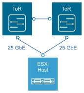
Each ESXi host is connected redundantly to the top of rack switches SDDC network fabric by two 25 GbE ports. Configure the top of rack switches to provide all necessary VLANs using an 802.1Q trunk. These redundant connections use features in vSphere Distributed Switch and NSX-T Data Center to guarantee that no physical interface is overrun, and available redundant paths are used. |
VLANs and Subnets in a Single VMware Cloud Foundation Instance with a Single Availability Zone
Each ESXi host uses VLANs and corresponding subnets.
Follow these guidelines:
Consider the use of /24 subnets to reduce confusion and mistakes when handling IPv4 subnet configuration.
Use the IP address of the floating interface from a first-hop redundancy protocol such as Virtual Router Redundancy Protocol (VRPP) or Hot Standby Routing Protocol (HSRP) as the gateway.
Use the RFC1918 IPv4 address space for these subnets and allocate one octet by VMware Cloud Foundation Instance and another octet by function.
Implement VLAN and IP subnet configuration according to the requirements of your organization.
VLANs and Subnets in a Single VMware Cloud Foundation Instance with Multiple Availability Zones
You deploy NSX Edge nodes in one of the clusters in a VI workload domain, usually the first cluster. The other clusters in the VI workload domain contain only customer workloads.
In the stretched edge and workload cluster, the management, Uplink 01, Uplink 02, and edge overlay networks in each availability zone must be stretched to facilitate failover of the NSX Edge appliances between availability zones. The Layer 3 gateway for the management and Edge overlay networks must be highly available across the availability zones.
Function |
First Availability Zone |
Second Availability Zone |
Highly Available Layer 3 Gateway Within the Zone |
Highly Available Layer 3 Gateway Across Zones |
|---|---|---|---|---|
Management - first availability zone |
✓ |
✓ |
✓ - across the first and second availability zones |
|
vSphere vMotion - first availability zone |
✓ |
✓ - first availability zone |
||
vSAN - first availability zone |
✓ |
✓ - first availability zone |
||
Host overlay - first availability zone |
✓ |
✓ - first availability zone |
||
Uplink01 |
✓ |
✓ |
||
Uplink02 |
✓ |
✓ |
||
Edge overlay |
✓ |
✓ |
✓ - across the first and second availability zones |
|
Management - second availability zone |
✓ |
✓ - second availability zone |
||
vSphere vMotion - second availability zone |
✓ |
✓ - second availability zone |
||
vSAN - second availability zone |
✓ |
✓ - second availability zone |
||
Host overlay - second availability zone |
✓ |
✓ - second availability zone |
Because other stretched clusters in the VI workload domain do not contain NSX Edge nodes, you do not need to stretch networks in these clusters.
Function |
First Availability Zone |
Second Availability Zone |
Highly Available Layer 3 Gateway Within the Zone |
Highly Available Layer 3 Gateway Across Zones |
|---|---|---|---|---|
Management - first availability zone |
✓ |
✓ - first availability zone |
||
vSphere vMotion - first availability zone |
✓ |
✓ - first availability zone |
||
vSAN - first availability zone |
✓ |
✓ - first availability zone |
||
Host overlay - first availability zone |
✓ |
✓ - first availability zone |
||
Management - second availability zone |
✓ |
✓ - second availability zone |
||
vSphere vMotion - second availability zone |
✓ |
✓ - second availability zone |
||
vSAN - second availability zone |
✓ |
✓ - second availability zone |
||
Host overlay - second availability zone |
✓ |
✓ - second availability zone |
VLANs and Subnets for Multiple VMware Cloud Foundation Instances
In a deployment with multiple VMware Cloud Foundation instances, add VLANs for remote tunnel end point (RTEP) traffic for the NSX Edge nodes in each VMware Cloud Foundation instance. Edge RTEP VLANs carry VMware Cloud Foundation instance-to-instance dataplane traffic. An Edge RTEP VLAN must be routed to the Edge RTEP VLANs in all other VMware Cloud Foundation instances.
Take into account the following considerations:
The RTEP network segment has a VLAN ID and Layer 3 range that are specific to the VMware Cloud Foundation instance.
In a single VMware Cloud Foundation instance with multiple availability zones, the RTEP network segment must be stretched between the zones and assigned the same VLAN ID and IP range.
Function |
First Availability Zone |
Second Availability Zone |
Highly Available Layer 3 Gateway |
|---|---|---|---|
Edge RTEP in the first VMware Cloud Foundation instance |
✓ |
✓ |
✓ - across the first and second availability zones |
Edge RTEP in the VMware Cloud Foundation instance |
✓ |
X |
✓ |
Each VMware Cloud Foundation instance needs its own unique Layer 2 VLAN for the Edge RTEP network. All Edge RTEP networks must be reachable from each other.
The RTEP network is only needed for VI Workload Domain clusters which will contain NSX Edge Nodes. The RTEP network does not need to be presented to VI Workload Domain clusters which will not contain NSX Edge Nodes.
Physical Network Requirements
Physical requirements determine the MTU size for networks that carry overlay traffic, dynamic routing support, time synchronization through an NTP server, and forward and reverse DNS resolution.
Requirement |
Comment |
|---|---|
Use 25 GbE (10 GbE minimum) port on each ToR switch for ESXi host uplinks. Connect each host to two ToR switches. |
25 GbE provides required bandwidth for hyperconverged networking traffic. Connection to two ToR switches provides redundant physical network paths to each host. |
Provide an MTU size of 1,700 bytes or greater on any network that carries Geneve overlay traffic. |
Geneve packets cannot be fragmented. The MTU size must be large enough to support the extra encapsulation overhead. Geneve is an extensible protocol, therefore the MTU size might increase with future capabilities. While 1,600 bytes is sufficient, an MTU size of 1,700 bytes provides more room for increasing the Geneve MTU without the need to change physical infrastructure MTU. This design uses an MTU size of 9,000 bytes for Geneve traffic. |
Enable BGP dynamic routing support on the upstream Layer 3 devices. Consider the following requirements for the BGP configuration:
|
You use BGP on the upstream Layer 3 devices to establish routing adjacency with the Tier-0 service routers (SRs). NSX-T Data Center supports only the BGP routing protocol with NSX Federation. Dynamic routing enables ECMP failover for upstream connectivity. |
BGP Autonomous System Number (ASN) allocation |
A BGP ASN must be allocated for the SDN in NSX-T Data Center. Use a private ASN according to RFC1930. |
Physical Network Design Decisions
The design decisions you make for the physical network determine the physical layout and use of VLANs. They also include decisions on jumbo frames and on other network-related requirements such as DNS and NTP.
| Decision ID |
Design Decision |
Design Justification |
Design Implication |
|---|---|---|---|
| VCF-WLD-NSX-PHY-001 |
Use two ToR switches for each rack. |
Supports the use of two 10 GbE (25 GbE or greater recommended) links to each server and provides redundancy and reduces the overall design complexity. |
Requires two ToR switches per rack which can increase costs. |
| VCF-WLD-NSX-PHY-002 |
Implement the following physical network architecture:
|
|
|
| VCF-WLD-NSX-PHY-003 |
Do not use EtherChannel (LAG, LACP, or vPC) configuration for ESXi host uplinks |
|
None. |
| VCF-WLD-NSX-PHY-004 |
Use a physical network that is configured for BGP routing adjacency |
|
Requires BGP configuration in the physical network. |
Access Port Network Settings
Configure additional network settings on the access ports that connect the ToR switches to the corresponding servers.
Setting |
Value |
|---|---|
Spanning Tree Protocol (STP) |
Although this design does not use the STP, switches usually include STP configured by default. Designate the access ports as trunk PortFast. |
Trunking |
Configure the VLANs as members of an 802.1Q trunk. Optionally, the management VLAN can act as the native VLAN. |
MTU |
|
DHCP Helper |
Configure a DHCP helper (sometimes called a DHCP relay) on all TEP VLANs. Set the DHCP helper (relay) to point to a DHCP server by IPv4 address. If DHCP is not available, you can use static IP assignment. However, you will be unable to stretch the the cluster across availability zones. |
| Decision ID |
Design Decision |
Design Justification |
Design Implication |
|---|---|---|---|
| VCF-WLD-NSX-PHY-005 |
Assign persistent IP configurations to each management component in the SDDC with the exception for NSX tunnel endpoints (TEPs) that use dynamic IP allocation. |
Ensures that endpoints have a persistent management IP address. In VMware Cloud Foundation, you assign storage (vSAN and NFS) and vSphere vMotion IP configurations by using user-defined network pools. |
Requires precise IP address management. |
| VCF-WLD-NSX-PHY-006 |
Set the lease duration for the DHCP scope for the host overlay network to at least 7 days. |
IP addresses of the host overlay VMkernel ports are assigned by using a DHCP server.
|
Requires configuration and management of a DHCP server. |
| VCF-WLD-NSX-PHY-007 |
Use VLANs to separate physical network functions. |
|
Requires uniform configuration and presentation on all the trunks that are made available to the ESXi hosts. |
Jumbo Frames
IP storage throughput can benefit from the configuration of jumbo frames. Increasing the per-frame payload from 1,500 bytes to the jumbo frame setting improves the efficiency of data transfer. You must configure jumbo frames end-to-end. Select an MTU that matches the MTU of the physical switch ports.
According to the purpose of the workload, determine whether to configure jumbo frames on a virtual machine. If the workload consistently transfers large amounts of network data, configure jumbo frames, if possible. In that case, confirm that both the virtual machine operating system and the virtual machine NICs support jumbo frames.
Using jumbo frames also improves the performance of vSphere vMotion.
The Geneve overlay requires an MTU value of 1,600 bytes or greater.
| Decision ID |
Design Decision |
Decision Justification |
Decision Implication |
|---|---|---|---|
| VCF-WLD-NSX-PHY-008 |
Set the MTU size to at least 1700 bytes (recommended 9,000 bytes for jumbo frames) on the physical switch ports, vSphere Distributed Switches, vSphere Distributed Switch port groups, and N-VDS switches that support the following traffic types:
|
|
When adjusting the MTU size, you must also configure the entire network path (VMkernel ports, virtual switches, physical switches, and routers) to support the same MTU size. |
Networking for a Single VMware Cloud Foundation Instance with Multiple Availability Zones
Component |
Requirement |
|---|---|
MTU |
|
Layer 3 gateway availability |
For VLANs that are stretched between availability zones, configure data center provided method, for example, VRRP or HSRP, to fail over the Layer 3 gateway between availability zones. |
DHCP availability |
For VLANs that are stretched between availability zones, provide high availability for the DHCP server so that a failover operation of a single availability zone will not impact DHCP availability. |
BGP routing |
The data center of each availability zone data center must be configured with an Autonomous System Number (ASN). The ASN can be unique or identical between the availability zone. |
Ingress and egress traffic |
|
Latency |
|
Decision ID |
Design Decision |
Design Justification |
Design Implication |
|---|---|---|---|
VCF-WLD-NSX-PHY-009 |
Set the MTU size to at least 1700 bytes (recommended 9000 bytes for jumbo frames) on physical inter- availability zone networking components which are part of the networking path between availability zones for the following traffic types.
|
|
When adjusting the MTU size, you must also configure the entire network path (VMkernel ports, virtual switches, physical switches, and routers) to support the same MTU size. In multi-AZ deployments, the MTU must be configured on the entire network path between AZs. |
VCF-WLD-NSX-PHY-010 |
Configure VRRP, HSRP, or another Layer 3 gateway availability method. |
Ensures that the VLANs that are stretched between availability zones are connected to a highly- available gateway if a failure of an availability zone occurs. Otherwise, a failure in the Layer 3 gateway will cause disruption in traffic in the SDN setup. |
Requires configuration of a high availability technology for the Layer 3 gateways in the data center. |
Networking for VMware Cloud Foundation Instances
For a topology with multiple VMware Cloud Foundation instances, specific requirements for the networking in a data center and between data centers exist. These requirements extend those for an environment with a single availability zone and those for multiple availability zones.
Component |
Requirement |
|---|---|
MTU |
|
BGP Routing |
|
Ingress and egress traffic |
|
Latency |
In a VMware Cloud Foundation instance:
Between multiple VMware Cloud Foundation instances:
Maximum network latency between NSX Local Manager clusters must be 150 ms. |
Required connectivity between VMware Cloud Foundation instances |
|
Decision ID |
Design Decision |
Design Justification |
Design Implication |
|---|---|---|---|
VCF-WLD-NSX-PHY-011 |
Set the MTU size to at least 1,500 bytes (1,700 bytes preferred, 9,000 bytes recommended for jumbo frames) on the physical inter-instance network components which are part of the network path between availability zones for edge RTEP traffic. |
|
When adjusting the MTU packet size, you must also configure the entire network path, that is, virtual interfaces, virtual switches, physical switches, and routers to support the same MTU packet size. |
VCF-WLD-NSX-PHY-012 |
Provide a connection between VMware Cloud Foundation instances that is capable of routing between each NSX Manager cluster. |
Configuring NSX Federation requires connectivity between NSX Global Managers, NSX Local Managers, and NSX Edge clusters. |
Requires unique routable IP addresses for each region. |
VCF-WLD-NSX-PHY-013 |
Ensure that latency between regions is less than 150 ms |
A latency below 150 ms is required for the following features.
|
None. |
VCF-WLD-NSX-PHY-014 |
Provide BGP routing between all VMware Cloud Foundation instances. |
Automated failover of networks requires a dynamic routing protocol, such as BGP. |
None. |
