


NSX provides networking services to workloads in VMware Cloud Foundation such as load balancing, routing and virtual networking.
Component |
VMware Cloud Foundation Instances with a Single Availability Zone |
VMware Cloud Foundation Instances with Multiple Availability Zones |
|---|---|---|
NSX Manager Cluster |
|
|
NSX Global Manager Cluster (Conditional) |
|
|
NSX Edge Cluster |
|
|
Transport Nodes |
|
|
Transport zones |
|
|
VLANs and IP subnets allocated to NSX For information about the networks for virtual infrastructure management, see Distributed Port Group Design. |
||
Routing configuration |
|
|
For a description of the NSX logical component in this design, see NSX Logical Concepts and Components.
Single Instance - Single Availability Zone
The NSX design for the Single Instance - Single Availability Zone topology consists of the following components:
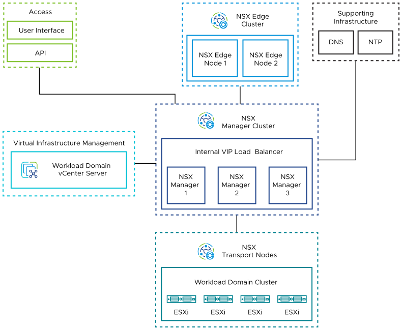
Unified appliances that have both the NSX Local Manager and NSX Controller roles. They provide management and control plane capabilities.
NSX Edge nodes in the workload domain that provide advanced services such as load balancing, and north-south connectivity.
ESXi hosts in the workload domain that are registered as NSX transport nodes to provide distributed routing and firewall services to workloads.
Single Instance - Multiple Availability Zones
The NSX design for a Single Instance - Multiple Availability Zone topology consists of the following components:
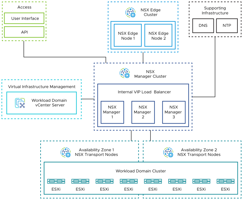
Unified appliances that have both the NSX Local Manager and NSX Controller roles. They provide management and control plane capabilities.
NSX Edge nodes that provide advanced services such as load balancing, and north-south connectivity.
ESXi hosts that are distributed evenly across availability zones in the workload domain and are registered as NSX transport nodes to provide distributed routing and firewall services to workloads.
Multiple Instances - Single Availability Zone
The NSX design for a Multiple Instance - Single Availability Zone topology consists of the following components:
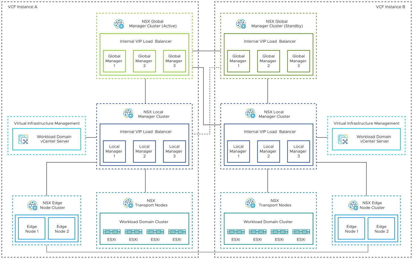
Unified appliances that have both the NSX Local Manager and NSX Controller roles. They provide management and control plane capabilities.
NSX Edge nodes that provide advanced services such as load balancing, and north-south connectivity.
ESXi hosts in the workload domain that are registered as NSX transport nodes to provide distributed routing and firewall services to workloads.
NSX Global Manager cluster in each of the first two VMware Cloud Foundation instances.
You deploy the NSX Global Manager cluster in each VMware Cloud Foundation instance so that you can use NSX Federation for global management of networking and security services.
An additional infrastructure VLAN in each VMware Cloud Foundation instance to carry instance-to-instance traffic (RTEP).
Multiple Instances - Multiple Availability Zones
The NSX design for a Multiple Instance - Multiple Availability Zone topology consists of the following components:
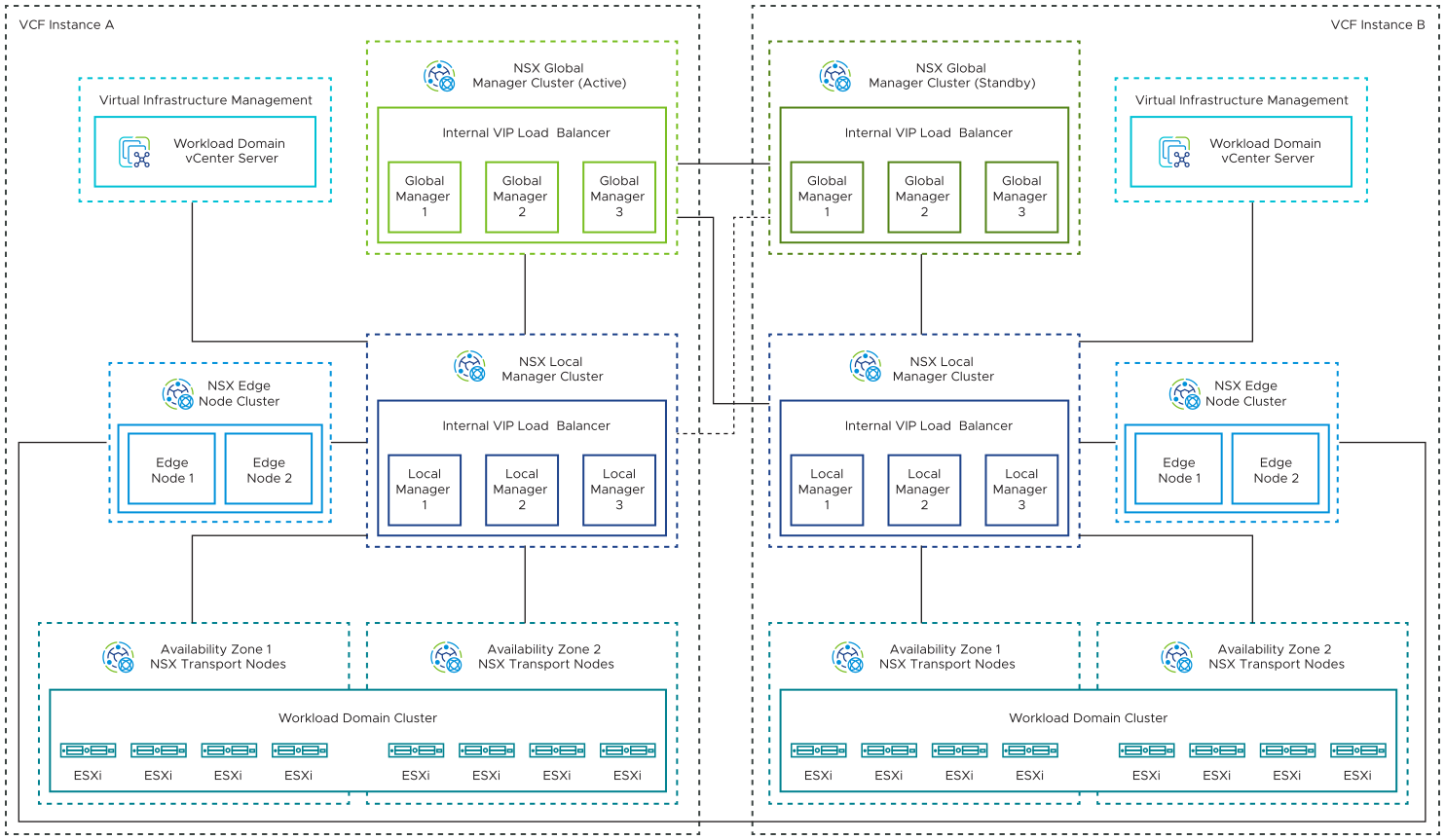
Unified appliances that have both the NSX Local Manager and NSX Controller roles. They provide management and control plane capabilities.
NSX Edge nodes that provide advanced services such as load balancing, and north-south connectivity.
ESXi hosts that are distributed evenly across availability zones in the workload domain in a VMware Cloud Foundation instance, and are registered as NSX transport nodes to provide distributed routing and firewall services to workloads.
NSX Global Manager cluster in each of the first two VMware Cloud Foundation instances.
You deploy the NSX Global Manager cluster in each VMware Cloud Foundation instance so that you can use NSX Federation for global management of networking and security services.
An additional infrastructure VLAN in each VMware Cloud Foundation instance to carry instance-to-instance traffic (RTEP).
