


As part of the overlay design, you determine the NSX configuration for handling traffic between workloads, management or customer, in VMware Cloud Foundation. You determine the NSX segments and the transport zones.
Logical Overlay Design for VMware Cloud Foundation
This logical design provides the network virtualization design of the logical components that handle the data to and from the workloads in the environment. For an environment with multiple VMware Cloud Foundation instances, you replicate the design of the first VMware Cloud Foundation instance to the additional VMware Cloud Foundation instances.
ESXi Host Transport Nodes
A transport node in NSX is a node that is capable of participating in an NSX data plane. The workload domains contain multiple ESXi hosts in a vSphere cluster to support management or customer workloads. You register these ESXi hosts as transport nodes so that networks and workloads on that host can use the capabilities of NSX. During the preparation process, the native vSphere Distributed Switch for the workload domain is extended with NSX capabilities.
Virtual Segments
Geneve provides the overlay capability to create isolated, multi-tenant broadcast domains in NSX across data center fabrics, and enables customers to create elastic, logical networks that span physical network boundaries, and physical locations.
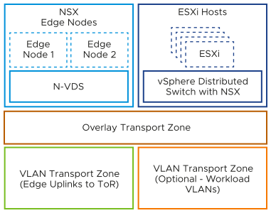
Transport Zones
A transport zone identifies the type of traffic, VLAN or overlay, and the vSphere Distributed Switch name. You can configure one or more VLAN transport zones and a single overlay transport zone per virtual switch. A transport zone does not represent a security boundary. VMware Cloud Foundation supports a single overlay transport zone per NSX Instance. All vSphere clusters, within and across workload domains that share the same NSX instance subsequently share the same overlay transport zone.
Host Transport Node Profiles
A transport node profile (TNP) is a template to define networking configuration that is applied to a host cluster. It contains an uplink profile, transport zones, and an IP assignment method together with vSphere Distributed Switch-to-NSX uplink mappings. After you create a TNP, you attach it to a cluster. As a result, the NSX configurations defined in the profile are applied to the nodes in the cluster.
Uplink Policy for ESXi Host Transport Nodes
Uplink profiles define policies for the links from ESXi hosts to NSX segments or from NSX Edge appliances to top of rack switches. By using uplink profiles, you can apply consistent configuration of capabilities for network adapters across multiple ESXi hosts or NSX Edge nodes.
Uplink profiles can use either load balance source or failover order teaming. If using load balance source, multiple uplinks can be active. If using failover order, only a single uplink can be active.
Sub-Transport Node Profiles
A sub-transport node profile (TNP) is a template to define networking for a subset of hosts in a cluster, also known as sub-cluster. This construct is useful for stretched clusters or multi-rack clusters with Layer 3 networking so that the nodes in each availability zone or each rack in a multi-rack configuration can have different network configuration for host TEP VLANs and subnets.
Replication Mode of Segments
The control plane decouples NSX from the physical network. The control plane handles the broadcast, unknown unicast, and multicast (BUM) traffic in the virtual segments.
The following options are available for BUM replication on segments.
BUM Replication Mode |
Description |
|---|---|
Hierarchical Two-Tier |
The ESXi host transport nodes are grouped according to their TEP IP subnet. One ESXi host in each subnet is responsible for replication to an ESXi host in another subnet. The receiving ESXi host replicates the traffic to the ESXi hosts in its local subnet. The source ESXi host transport node knows about the groups based on information it has received from the control plane. The system can select an arbitrary ESXi host transport node as the mediator for the source subnet if the remote mediator ESXi host node is available. |
Head-End |
The ESXi host transport node at the origin of the frame to be flooded on a segment sends a copy to every other ESXi host transport node that is connected to this segment. |
Overlay Design Requirements and Recommendations for VMware Cloud Foundation
Consider the requirements for the configuration of the ESXi hosts in a workload domain as NSX transport nodes, transport zone layout, uplink teaming policies, and the best practices for IP allocation and BUM replication mode in a VMware Cloud Foundation deployment.
Overlay Design Requirements
You must meet the following design requirements in your overlay design.
Requirement ID |
Design Requirement |
Justification |
Implication |
|---|---|---|---|
VCF-NSX-OVERLAY-REQD-CFG-001 |
Configure all ESXi hosts in the workload domain as transport nodes in NSX. |
Enables distributed routing, logical segments, and distributed firewall. |
None. |
VCF-NSX-OVERLAY-REQD-CFG-002 |
Configure each ESXi host as a transport node using transport node profiles. |
|
None. |
VCF-NSX-OVERLAY-REQD-CFG-003 |
To provide virtualized network capabilities to workloads, use overlay networks with NSX Edge nodes and distributed routing. |
|
Requires configuring transport networks with an MTU size of at least 1,600 bytes. |
VCF-NSX-OVERLAY-REQD-CFG-004 |
Create a single overlay transport zone in the NSX instance for all overlay traffic across the host and NSX Edge transport nodes of the workload domain or multiple workload domains using a shared NSX instance. |
|
All clusters in all workload domains that share the same NSX Manager share the same overlay transport zone. |
VCF-NSX-OVERLAY-REQD-CFG-005 |
Create an uplink profile with a load balance source teaming policy with two active uplinks for ESXi hosts. |
For increased resiliency and performance, supports the concurrent use of both physical NICs on the ESXi hosts that are configured as transport nodes. |
None. |
Requirement ID |
Design Requirement |
Justification |
Implication |
|---|---|---|---|
VCF-NSX-L3MR-OVERLAY-REQD-CFG-001 |
Create an uplink profile for each rack with a separate host TEP transport VLAN ID per rack. |
Enables a Layer 3 boundary at the top-of-rack switches for host TEP traffic. |
Requires additional host TEP VLAN ID per rack. |
VCF-NSX-L3MR-OVERLAY-REQD-CFG-002 |
Create a host TEP IP pool for each rack with a subnet allocated per rack and a gateway for the subnet. |
|
Requires additional subnet per rack. |
VCF-NSX-L3MR-OVERLAY-REQD-CFG-003 |
Create NSX host sub transport node profiles for additional racks. |
|
None |
Overlay Design Recommendations
In your overlay design for VMware Cloud Foundation, you can apply certain best practices.
Recommendation ID |
Design Recommendation |
Justification |
Implication |
|---|---|---|---|
VCF-NSX-OVERLAY-RCMD-CFG-001 |
Use static IP pools to assign IP addresses to the host TEP interfaces. |
|
None. |
VCF-NSX-OVERLAY-RCMD-CFG-002 |
Use hierarchical two-tier replication on all overlay segments. |
Hierarchical two-tier replication is more efficient because it reduced the number of ESXi hosts the source ESXi host must replicate traffic to if hosts have different TEP subnets. This is typically the case with more than one cluster and will improve performance in that scenario. |
None. |
Recommendation ID |
Design Recommendation |
Justification |
Implication |
|---|---|---|---|
VCF-NSX-OVERLAY-RCMD-CFG-003 |
Configure an NSX sub-transport node profile. |
|
Changes to the host transport node configuration are done at the vSphere cluster level. |
