The use cases at the Edge involves various key technologies and considerations including but not limited to vSAN, Tanzu Kubernetes Grid, ingress and load balancing, ESXi Real Time, GPU use cases, and edge native applications.
vSAN Requirements
An integral part of Enterprise Edge’s Hyperconverged Infrastructure (HCI) is vSAN – VMware’s software-defined storage solution that allows locally installed hard drives on ESXi hosts to be aggregated as a pool of storage to be shared among the hosts in the same cluster.
vSAN requires at least a Cache tier device and a Capacity tier device in a Disk Group. It can operate in an all-flash or hybrid configuration, whereas in a hybrid configuration, the Capacity tier can be low-cost SATA or SAS disk drives. The cache device must be a flash drive in either a hybrid or all-flash configuration. In a hybrid configuration, the cache device is utilized by vSAN as both a read cache (70%) and a write buffer (30%). In an all-flash configuration, 100% of the cache device is dedicated to write-buffering (up to a maximum of 600 GB). For reads in an all-flash configuration, the requested block can be read from the cache tier if it’s still hot, or it is read from the capacity tier otherwise.
In terms of networking requirements, vSAN supports a 1Gbps network but 10Gbps or higher throughput links are highly recommended. If you’re using an all-flash vSAN configuration, it requires 10Gbps bandwidth between the hosts. Network latency between hosts in a standard vSAN cluster must be less than 1 ms RTT for 3-node clusters. For two-node clusters, latency from the cluster to the vSAN witness must be less than 500ms RTT and it is recommended that the two hosts in the cluster are directly connected with a 10Gbps connection.
The Enterprise Edge reference designs will include edge deployments of one, two, and three-node clusters. Given 3 hosts is likely the maximum number of hosts in an Enterprise Edge cluster, RAID-1 with Failure to Tolerate or FTT=1 is the only supported configuration given RAID-5 and RAID-6 require a minimum of 4 and 6 nodes respectively. The table below demonstrates the minimum nodes required for the common RAID configurations. For three node clusters, the minimum requirement of 3 hosts for a quorum is met and witness components are distributed across all hosts. Losing a single host in a 3-node cluster will not cause any loss of data as there is an additional copy of the data on another device in a separate failure domain. For 2-node vSAN clusters leveraging a vSAN witness, a quorum is achieved with the vSAN witness and data will be mirrored on the two ESXi hosts. Similarly, losing a single host in the 2-node cluster will not result in data loss, though there will be no place to rebuild the missing components in the failed host. When applicable, it is advisable to consider having N+1 nodes which means for a 3-node cluster, you would have four hosts which will increase the failure domains and allow for vSAN self-healing in case of a host failure.
RAID |
Failures to Tolerate |
Minimum Nodes Required |
Minimum Recommended (N+1) |
|---|---|---|---|
RAID 1 |
FTT=1 |
3 |
4 |
RAID 5 |
FTT=1 |
4 |
5 |
RAID 1 |
FTT=2 |
5 |
6 |
RAID 6 |
FTT=2 |
6 |
7 |
Tanzu Kubernetes Grid vs. vSphere with Tanzu
VMware Tanzu enables administrators to deploy Tanzu Kubernetes Cluster using two different methods – Tanzu Kubernetes Grid (TKG) and vSphere with Tanzu. Tanzu Kubernetes Grid, sometimes referred to as TKGm, is an upstream conformant Kubernetes runtime from VMware that can be deployed across multiple platforms and Public Cloud providers including vSphere, AWS, Azure, and GCP. The rest of the documentation will refer to it by its abbreviation TKG. In comparison, vSphere with Tanzu is a method of deploying Kubernetes workloads natively on ESXi and brings with it tighter integration between Tanzu Kubernetes and vSphere. vSphere with Tanzu enables administrators to deploy Tanzu Kubernetes Clusters similar to what TKG allows you to do, but it also enables container pods to be run directly on the ESXi hosts along with traditional virtual machines. This ability to run Tanzu Kubernetes clusters natively on vSphere and managed by the Supervisor Cluster is sometimes referred to as Tanzu Kubernetes Grid Service or TKGS, not to be confused with TKG which is a multi-cloud offering.
This Enterprise Edge Reference Architecture guide will primarily focus on TKG for edge use cases due to the following advantages of TKGm:
TKG offers flexibility for where to place the Management Cluster relative to Tanzu Kubernetes Grid workload clusters at the Edge. Management Cluster is the first element required to deploy the TKG instance and create the TKG workload clusters.
vSphere with Tanzu (TKGS) does not have the flexibility and requires each Edge Cluster to have its local Supervisor cluster which serves the function of a Management Cluster. Enterprise Edge deployments recommend a Hub and Spoke topology and therefore TKG is the preferred method to run and operate Kubernetes on Enterprise Edge.
vSphere with Tanzu requires a minimum of 3 hosts in a cluster and that cannot be met by the one-node and 2-node edge sites.
TKG does not require NSX-T networking stack or NSX Advanced Load Balancer at the edge. Its advantage of a smaller footprint makes it a better fit for smaller Edge deployments.
Disconnected Edge
One of the aspects of the edge that we must consider is the potential for the edge sites to be disconnected for an extended time. It is expected that existing applications running in the Enterprise Edge clusters should continue to function. However, some of the management capabilities for the Enterprise Edge will be lost in terms of both infrastructure and workload management. The table below highlights some factors to consider for applications deployed at the edge site when it’s in a disconnected mode. The ‘Hub and Spoke’ and Hybrid topologies refer to architectures highlighted in the VMware Tanzu Edge Solution Architecture document. The ‘Hub and Spoke’ topology is recommended for Enterprise Edge deployments unless a Hybrid topology is required to run vCenter at each site and meet the requirements.
Hub and Spoke |
Hybrid |
|
|---|---|---|
Run existing application |
Yes |
Yes |
Deploy new application |
No |
Only if packages are available locally |
Upgrade the cluster |
No |
No |
Scale the cluster |
No |
No |
Authenticate with pinniped |
No (pinniped needs access to the TKG management cluster) |
No (pinniped needs access to the TKG management cluster) |
Create or move Persistent Volumes using vSphere CSI driver |
No |
Yes |
Impact of a single node failure (assuming there is more than one node) |
Application will be able to recover unless NSX ALB is used for load-balancing at the Edge |
Application might have a short disruption but will be able to cover |
Ingress and Load Balancing at the Edge
Ingress and load balancing for TKG workload clusters serve critical functions at the Edge as they are used to serve the applications running at the edge to users and endpoints outside of the cluster. In Kubernetes, Service, LoadBalancer, and Ingress constructs provide load-balancing capabilities at the edge. A Kubernetes Service is an abstraction that exposes an application running on a set of pods to external users. Kubernetes LoadBalancer is an extension of a Service and relies on the support of external load balancers. For example, vSphere can use the NSX Advanced Load Balancer when you create a Kubernetes service of type loadBalancer. The Kubernetes LoadBalancer extension operates at the L4 level and routes inbound traffic to the specified service.
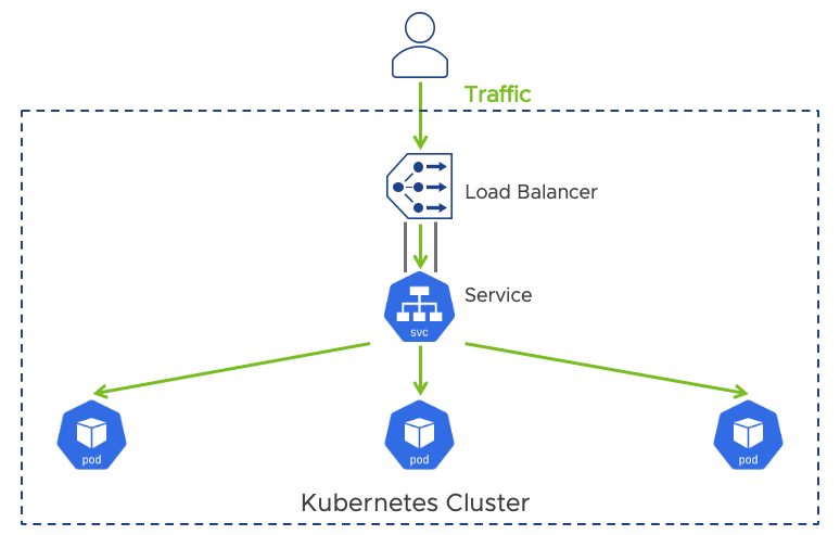
Here’s an example of how LoadBalancer is used with a Service object within cloud providers that supports external load balancers.
apiVersion: v1
kind: Service
metadata:
  name: my-service
spec:
  selector:
    app.kubernetes.io/name: MyApp
  ports:
    - protocol: TCP
      port: 80
      targetPort: 9376
  clusterIP: 10.0.1.239
  type: LoadBalancer
status:
  loadBalancer:
    ingress:
    - ip: 192.0.2.127
An Ingress in Kubernetes is an API object that routes traffic from outside the cluster to one or more services and leverages an Ingress controller to do so. Where a loadBalancer can only forward to one Service, an ingress can serve as a single point of entry for multiple applications. It operates at the L7 level and the ingress controller by default only routes HTTP and HTTPS-based traffic using a collection of routing rules. For example, the load balancer spun up by the ingress controller can support path-based and domain-based routing to backend services running in the cluster. While ingress controllers support routing to multiple applications, load-balancing TCP and UDP traffic using an Ingress is not supported by default and it can only reference services in the same namespace. Kubernetes does not include an ingress controller by default and there are many options available such as Contour, Avi Kubernetes Operator (AKO), and Nginx Ingress Controller.
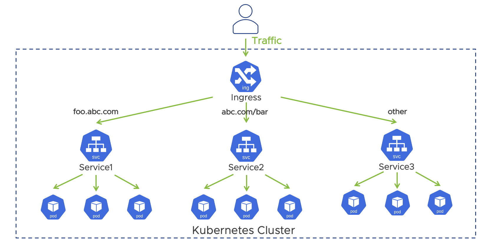
An example of an Ingress object is shown below.
apiVersion: extensions/v1beta1
kind: Ingress
metadata:
  name: my-ingress
spec:
  backend:
    serviceName: other
    servicePort: 8080
  rules:
  - host: foo.mydomain.com
    http:
      paths:
      - backend:
          serviceName: foo
          servicePort: 8080
  - host: mydomain.com
    http:
      paths:
      - path: /bar/*
        backend:
          serviceName: bar
          servicePort: 8080
For control plane load balancing on TKG workload clusters in Enterprise Edge, NSX Advanced Load Balancer or Kube-vip can be used to provide HA and the virtual IP address (VIP) for the master nodes. Both solutions utilize Service and loadBalancer constructs to serve as a load balancer for the control plane. Kube-vip is recommended given the NSX ALB requires the service engine and either a local ALB Controller involving a larger footprint or a remote ALB Controller in the data center that may impact control plane access when connectivity issues occur. Kube-vip is also recommended because it runs in the cluster and does not rely on an external VM or container.
Depending on the application, workload load balancing on TKG workload clusters can be achieved through either ingress controller or Service type loadBalancer. Kube-vip, specifically kube-vip Cloud Provider, is recommended for Service type loadBalancer for workload load balancing at the edge sites due to their small footprint and versatility. Contour is recommended as the ingress controller for TKG workload clusters and will often be used in conjunction with load balancers to meet the necessary load-balancing requirements. Although NSX ALB AKO can also serve as an ingress controller, it’s not recommended at the edge due to the same reasons discussed above.
ESXi Real-Time Use Cases
In the manufacturing and utility infrastructure verticals, use cases to virtualize real-time systems are emerging as IT and OT are converging at the edge. IT teams are looked upon to deliver a platform that simplifies the orchestration and operation of workloads, while OT teams are seeking to modernize and deliver applications and capabilities to address OT use cases. Some of these use cases demand what the industry calls “hard” real-time, which is a requirement for applications that are very sensitive to temporal precision and if violated, can lead to irrecoverable system damage. An example of this is the virtualization of Programmable Logic Controllers (PLCs) with high-speed sensors and motion control applications, which may require sub-1ms response time and deterministic outcome. Similarly, real-time hypervisor requirements exist in the utility infrastructure space as well in applications requiring equally stringent “hard” real-time characteristics.
Starting in ESXi 7.0 Update 2, real-time hypervisor features were introduced to reduce compute and I/O latency and jitter for latency-sensitive workloads. The optimizations reduce interference and jitter sources to provide a consistent runtime environment. For real-time workloads running on VMs configured with PCI-Passthrough and ESXi Real-time, nearly identical latency has been observed compared to results from the same application running on bare metal. The same result was seen even when other non-real-time workloads are running adjacent to the critical application on the same host.
The Reference Design section will cover the configuration and tuning of ESXi Real-time features for a virtual machine in vSphere.
GPU Uses Cases
GPUs are getting a lot of attention these days for many different use cases. There’s the data center use case where you’re performing bulk operations of AI/ML processing, training models, inferencing, and machine learning. At the edge, we’re finding the most unique applications of GPU utilization, specifically around computer vision. Deploying GPU on VM applications, utilizing GPU for containers running in Kubernetes, mixing them, and sharing the GPUs are all common implementations being explored at the edge.
In the retail segment, machine learning requirements driven by computer vision and fraud prevention are driving GPU usage on Edge platforms. For manufacturing, improving productivity and quality inspections are bringing new computer vision and machine learning applications needing GPU at the edge. Due to the cost and complexity of GPU operations, GPU sharing between workloads for optimal resource utilization is a prerequisite and GPU management in Kubernetes is becoming a growing requirement.
The GPU deployment options can be separated into 2 main categories – dedicated GPU and GPU sharing on the same host. Dedicated GPU is the concept of applying PCI passthrough and assigning a virtual machine the full capacity of the GPU card. It provides near-native performance and supports automated workload placement and HA but has the downside of underutilizing the GPU. GPU sharing on the other hand allows a GPU to be shared between VMs and containers through time slicing (vGPU) or advanced partitioning - i.e., NVIDIA multi-instance GPU mode (MIG). NVIDIA vGPU software is included in the NVIDIA AI Enterprise suite, which is certified for vSphere.
ESXi 7.0 Update 3 or later is required to support GPU sharing for NVIDIA Ampere-based GPUs. In the Reference Design, we will cover the deployment of vGPU sharing in vSphere and how to implement NVIDIA GPU Operator for GPU Management in Kubernetes.
Building and Deploying Custom Edge Native Applications
Similar to Cloud Native Applications, there is a focus on leveraging lean/agile practices, modern application architectures, and DevOps for building and deploying Edge Native Applications. However, some differences need to be considered when architecting and deploying modern applications to the edge.
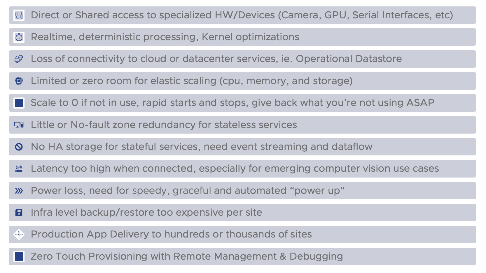
Factors differentiating edge native applications from cloud-native applications:
Data considerations for Edge Native Applications
Data requirements for applications running at the edge may very well be the number one driver of the costs associated with running and operating hundreds or thousands of sites. While VMware, together with numerous hardware and software partners, can provide very robust solutions for the most critical data center workloads, we are very keen on making sure the edge architecture is designed with just enough data protection, hardware redundancy, and computing. When architecting new applications or modernizing existing workloads, it is important to understand (1) what specific data originates from an individual edge location and (2) whether it is business-critical data that it cannot be lost. It is usually assumed that all data at the edge may not share these 2 criteriums. For example, a Retailer’s SKU and pricing information is usually something that is managed as a corporate function. Therefore, the data originates from a system in a data center or cloud and gets pushed out to brick-and-mortar retail locations so that it can be queried as fast as possible during checkout. In this scenario, the data is already protected in corporate systems and can be re-retrieved in the event of an outage at a retail location. However, point-of-sale transaction data is absolutely data having the 2 criteria. Another example that may be more subtle to classify is sensor data collected in an industrial facility. While this data is uniquely generated and originates from the edge location, individual data points from a sensor may not be considered business-critical because they are constantly collected. In some cases, a gap in data points is acceptable. How does this relate to the cost of implementing edge? Consider costs for implementing Highly available storage with local disaster recovery solutions. This would require additional infrastructure resources locally available, such as storage backup solutions.
As an alternative to traditional disaster recovery, consider isolating data needing protection with a lightweight data service, such as VMware Postgres DB if SQL is required, or a store-and-forward streaming solution such as VMware RabbitMQ. VMWare PostgreSQL supports automation of database backup to cloud object storage such as any S3-compliant solution or Azure Blob Storage. RabbitMQ on the other hand supports WAN-friendly replication of data from the edge to the cloud or data using RabbitMQ Shovel. For all other data, whether corporate data or system configuration, we recommend reprovisioning rather than data recovery. In this way, we can limit the expense associated with a full storage DR solution by isolating edge-originating data from centrally managed system config or corporate data. We only need to protect the data originating from the edge.
Delivery of Edge Native
Delivering applications to thousands of edge locations adds a lot of choreography complexity on top of standard CI/CD delivery. The complexities with an edge highlight the need for a robust Supply Chain framework that sits above many of the interrelated steps when going from code commit to apps running at numerous production locations. To help streamline and templatize this overarching supply chain, VMware is investing in a couple of open-source projects calledCartographer and Carvel Tools.
Cartographer is a software supply chain choreographer. It can sometimes be confused with CI/CD tools. Cartographer is different in that it is orchestrating the process at a higher level than what CI/CD processes are focused on and in fact, works with integration to these known tools. For example, developers may only be focused on building and testing their apps within their Continuous Integration process. However, as standard practice, it is expected that Source code scanning and Container image scanning must also happen before and after CI. A software supply chain allows for the integration of developer-owned CI processes and can enforce the standard requirement for all apps to be scanned with integration with scanning technologies such as Grype or Snyk for example.
When implementing Supply Chain for the edge, there are 2 possible strategies:
Push model – uses a centralized process running in the cloud or corporate data center that remotely connects to the thousands of edge points to push out updates to applications.
Pull model – lightweight orchestration runs locally at each edge site, possibly along with a lightweight container registry allowing for container images to be carefully staged before updating.
While there are pros and cons associated with each mode, VMware recommends that customers evaluate the Pull model first. If the edge environment does have additional CPU and memory capacity for running Cartographer locally, the process likely going to be more reliable, especially in cases where not all edge locations benefit from having large bandwidth, low latency, and nearly flawless availability.
VMware packages Cartographer and Carvel Tools along with other supporting orchestration toolings such as Tekton and FluxCD Source Controller in a commercial offering called Tanzu Application Platform (TAP). TAP is focused on simplifying the use of Kubernetes for building and deploying customer-built applications. The idea is to improve the developer and DevOps experience which in turn drives productivity, security, and quality of software delivery. In this paper, we are only going to focus on the last-mile delivery mechanism for making app updates at the edge.
List of TAP components used for Edge Native App delivery:
Component |
Role |
Edge Resource needs |
|---|---|---|
Cartographer |
Allows users to create secure, reusable supply chains. Orchestrates the steps needed to rollout an app update at the edge site once triggered by FluxCD Source Controller |
4 Millicores/80 MB |
Tekton |
Perform auxiliary Tasks, such as relocating images from central datacenter to local edge registry |
4 Millicores/75 MB |
Kapp controller |
Monitors git repository for commits and applies deliverable artifacts |
72 Millicores/1.2GB |
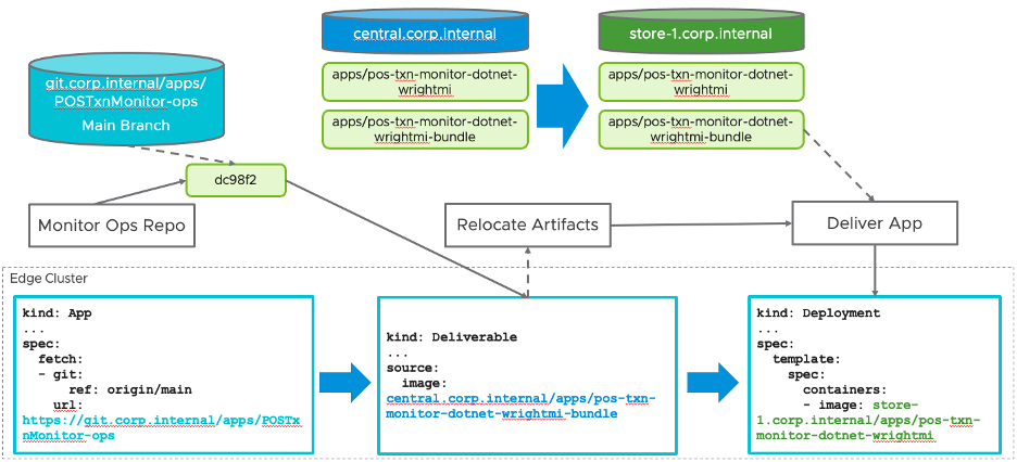
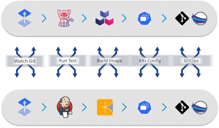
The following diagram illustrates the process that gets triggered when a commit occurs on a specific branch of a repository. The repository only contains the deployment YAML of type Deliverable. To set up the monitor of this repository and kick off the process, we have an App object deployed that references the GitHub URL. Upon a new commit, the kapp-controller fetches the new Deliverable and submits it to the edge cluster. With customization to the default Supply Chain, the first step at the edge is to relocate update container images down to the local edge registry. Notice that for this single application we have 2 container images being relocated:
pos-txn-monitor-dotnet-wrightmi– the containerized .NET 6 application generated from our automated build process in the datacenterpos-txn-monitor-dotnet-wrightmi-bundle– a non-runnable image containing the corresponding Kubernetes deployment object templates (Deployment, Service, ConfigMap, etc.). This image was also built by TAP supply chain steps which execute in the data center/cloud as a result of new builds.
Note that because TAP builds container images into layers, each time there is an update to the application, only the layer that is modified as a result of the change needs to be propagated to the edge locations (unless this is the first time being deployed). Relocating only the layer that changed lessens the network burden for constrained connectivity from the central registry to the edge registry. To learn more about how TAP builds container images from code, please see the documentation for Tanzu Build Service.
The final step to update the application is to extract the package bundle and apply the resulting Kubernetes YAML with an updated reference to the new .NET app container image.
To learn more about the entire build process and developer experience, please refer to the Tanzu Application Platform documentation.