


The 2-Node cluster is a small Enterprise Edge HCI with vSAN for storage, requiring a witness appliance. An external/integrated router/firewall is needed for networking. Each vSphere host should use 2 NICs for links to TOR switches, and 2 NICs for Direct Connect to each other. Use vSphere Distributed Switch, EtherChannel/LACP, and DVS uplinks for networking and vSAN.
Infrastructure and Networking
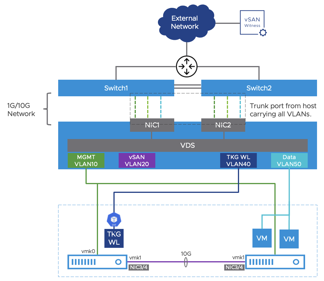
The 2-Node cluster is the smallest Enterprise Edge HCI that supports highly available compute, storage, and networking. It utilizes vSAN for storage and requires a vSAN witness appliance to store the witness components for a quorum. An external or integrated router or firewall will provide networking services and routing for the VMs and workloads deployed in the cluster. Each vSphere host should use 2 NICs for separate links to the TOR switches, and 2 additional NICs for Direct Connect to each other for vSAN networking.
Similar to a single node, the 2-node cluster should leverage vSphere Distributed Switch (VDS) for networking and create the four VLANs and the uplink (trunk port) in VDS. If the switches are stacked and support EtherChannel for higher availability and bandwidth, configure a link aggregation group (LAG) for connectivity to the TOR switches and add the physical uplinks to the LAG from each host. The same VDS and LAG can be used for both hosts. Ensure the TOR switches have matching EtherChannel and layer 2 configurations on their ports. You can find more information about link aggregation in ESXi from this KB. If the TOR switches do not support EtherChannel, bypass LACP and NIC Teaming configurations and simply configure the vmnics as DVS uplinks.
For vSAN networking, create a LAG backed by the two Direct Connect links bonded as a single EtherChannel. This design will allow both links to be active and LACP load balancing will help with the load balancing of vSAN traffic across those links.
A reference network design is provided with the following requirements:
Use a minimum of two NICs per host to connect to the top of rack (TOR) switches. Each NIC should connect to a different switch for redundancy.
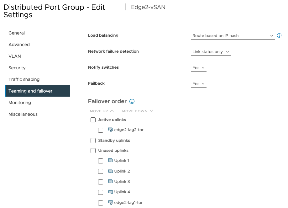
If the TOR switches are stacked and/or support EtherChannel, configure LACP for the uplinks in VDS and enable NIC Teaming and Failover for workload port group; use ‘Route based on IP hash’ for the load balancing setting. This is optional.
The upstream network device will serve as the DHCP server and default gateway for the four VLAN subnets and advertise the network prefixes to the data center.
For vSAN networking, use two 10Gbps Direct Connect links between the two hosts. A separate VMkernel interface (vmk1) will map to the configured vSAN port group with a single logical uplink (LAG) which is backed by the two Direct Connect links bonded together by LACP.
Both vmk0 and vmk1 interfaces can be designated to carry traffic destined for the vSAN Witness appliance. Witness traffic must be enabled from the host CLI using
esxcli vsan network ip add -i vmk1 -T=witness.TKG Management Cluster in the data center must have connectivity to ‘TKG WL’ VLAN to configure the workload clusters.
Internet access for the pods in the TKG workload clusters.
Notice the diagram shows VDS network configuration for only one host. Therefore, each host in the cluster will have 2 vmnic that connect to the switches and 2 vmnics for Direct Connect. Two LAGs have to be created in VDS corresponding to the two sets of vmnic, in which each set of uplinks is bonded in a LAG allowing both links to be active. The two Direct Connect links should only be used for vSAN and other host services. The bonded LAGs can then be used by the port groups as uplinks in the ‘Teaming and failover’ settings. An example of configuring a LAG for the vSAN port group is shown in the following diagram.
vSphere HA and DRS
As discussed previously in Edge architecture, vSphere HA and DRS will provide computing high availability and orchestrate virtual machine distribution in the vSphere cluster. DRS will load balance virtual machines and TKG nodes based on host utilization and vSphere HA will handle the failover of the TKG control plane and worker nodes in case of host failures. As of vSphere version 7.0U3, vSphere HA does not work for Virtual machines configured with real-time attributes.
Workload Clusters
The TKG workload clusters will be brought up by the TKG management cluster in the data center. For a 2-node cluster, the recommendation is to run a single master node in the TKG workload cluster and leverage vSphere HA and vSAN for failover in the event of a host or VM failure. The decision of the number of worker nodes to deploy in the TKG cluster does not change.
Integrated SD-WAN
Every Enterprise Edge site requires networking services for management, tools, and applications running in the Virtual machines and containers. For 2-node clusters, a pair of switches and upstream routers or firewalls are typically needed for routing, VLANs, and networking services. Deploying virtual SD-WAN appliances on the Enterprise Edge assumes those functions and removes the need for those external appliances.
The integrated SD-WAN as a virtual network function (VNF) will need to meet or supplement the following functions:
Deliver highly available networking for management, tools, and Virtual machines and containers in the Enterprise Edge.
Serve as the default DHCP, DNS, and NTP server for workloads running in each of the VLANs.
Minimize physical footprint and eliminate the TOR switches and upstream routers and firewalls.
Provide VPN connectivity to the data center for Enterprise Edge sites with no private circuits and optimize application performance.
Facilitate dynamic routing for edge subnets, allowing the TKG management cluster to provision Edge workload clusters.
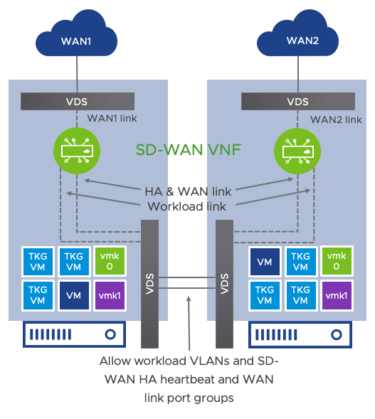
Using the diagram below as a reference design for the 2-node cluster, a pair of highly available VMware SD-WAN virtual Edges will be deployed as VMs on each of the hosts. They will operate in Enhanced HA mode in which the hosts in the cluster are connected to disparate WAN circuits – i.e., host-1 connected to WAN1 and host-2 connected to WAN2. The pair of SD-WAN virtual appliances are active/standby from the control plane perspective and active/active in the data plane, meaning only one of the SD-WAN appliances will be active and forwarding traffic at a time, but both WAN circuits will be utilized simultaneously. The reference design achieves this by connecting the SD-WAN appliance to all the workload VLANs and then allowing those port groups and their HA and WAN link port groups through the Direct Connect uplinks between the hosts. This topology supports a setup where VMs in host-1 can use SD-WAN appliance #2 as the default gateway and its networking services and enables SD-WAN appliance #2 to be virtually connected to WAN1 and build overlays across it. Allowing the SD-WAN HA link and WAN link port groups through the Direct Connect 10+Gbps links (LAG recommended) will automatically enact the Enhanced HA features in SD-WAN.
With the SD-WAN appliances serving as the upstream router/firewall for the vSphere cluster, the vmk0 interface used for management communication to the vCenter will also have to use the SD-WAN VNFs as the default next-hop for routing so the hosts can reach the vCenter. The following steps shall be followed to ensure the host management connection is properly configured:
Ensure an out-of-band connection (IPMI) is available to both servers.
Configure VDS, port groups, uplinks, and Direct Connect interfaces as discussed in the reference design.
Enable the “MAC address changes” option in security settings for all the port groups connected to the SD-WAN VNF except the HA link port group. Change the security setting on the HA link port group to allow for “Promiscuous mode”. These settings are required because SD-WAN leverages virtual MAC addresses and utilizes multicast. You can find more information in this KB article.
Provision SD-WAN virtual Edge on each vSphere host and allow the appropriate port groups on the uplinks or LAGs. Verify that both VMs are connected to all the workload, HA, and respective WAN link port groups.
Active the SD-WAN VNFs and ensure they’re operating in Enhanced HA mode from the VMware SD-WAN Orchestrator.
Migrate the vmk0 network adapter to VDS and set its next hop to be the SD-WAN VNF. If routing was set up correctly, management traffic will be forwarded through the SD-WAN overlay.
Besides reducing the physical footprint at the edge sites, integrated SD-WAN greatly simplifies secured and encrypted network connectivity from the edge site to the data center and other edges.
