The benefits of having signal translation devices, such as MUs, transmitting and receiving data using standard communication protocols, against using proprietary or limited point-to-point architectures, must be well understood. IEC 61850 is a very mature standard that consists of multiple types of protocol mechanisms.
The relevant protocols for vPAC are defined in Glossary of Terms, and all use multicast packet distribution.
Standard IEC 61869-9:2016 offers a more efficient means for transmitting sampled values against the IEC 61850-9-2LE guideline. In contrast to the EC 61850-9-2LE guideline for SV packets to contain one set of four individual phase currents, with four individual phase voltage measurements, 61869-9 offers configurable construction of a message containing multiple Application Service Data Units (ASDUs). Additionally, it maintains backwards compatibility with the 9-2LE definitions.
These aspects aid in the economical and physical integration feasibility of deploying MUs to support a software-defined substation application architecture.
As the initial VMs tested only support 9-2LE currently, wider 9-9 support is actively being integrated into forthcoming appliances.
Two major considerations remain regarding the inherent capabilities and placement of MUs.
Simplicity in Merging Units
Most of the commercially available Merging Units (MU) at present remain functionally like microprocessor relays. Therefore, they might offer a multitude of configurable settings, like the previous generation of grid devices. It is often suggested that these IEDs might be positioned to provide backup protection for a virtual appliance. However, their deployment adjacent to a virtual system adds a level of complexity and increased commissioning needs, along with requiring a higher level of maintenance.
A simplistic, modular merging unit design is best suited to support a software-defined architecture. With a focus to achieve simple signal translation through standard protocols within a harsh environment for sustained periods of time, an optimal design can be achieved. This design then supports the intelligence and flexibility of the substation-centralized compute, which already offers new layers of redundancy and resiliency, while are administered from within a common toolset.

This type of MU helps end users in monetarily justifying their migratory technology business case in the near term and provide cost and time benefits and architectural simplification in the long-term during maintenance and future upgrade activities.
An MU can also take the form of a virtual merging unit or virtual processing interface that uses simple, robust modules without the need for complex configuration (if any is required). Signals are collected within a software-defined aggregator to publish consolidated, standardized sampled values (for example, IEC 61869-9 formatted) and makes it easier to locate the merging unit for each component, to only measure the signals for each high voltage apparatus.
Installation Location
Merging units are often considered for installation outdoors, nearest high voltage apparatus. It positions them in the substation yard, external to the control building. There are advantages to this approach, including:
Safer overall secondary circuitry (fiber communications traversing from MU to a software-defined infrastructure) with reduced exposure to current, voltage, and auxiliary power signals.
Reduced equipment footprint in control buildings.
Less utility cabling and termination quantities (especially true if MU is procured with apparatus).

One disadvantage here is the higher exposure to volatile environmental conditions, especially in climates including extreme heat or cold.
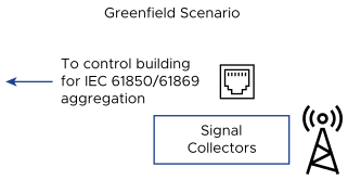
This approach might be easier to justify in greenfield scenarios where all construction is new. In this case, some installation labor can be provided through equipment procurement, and the deployment of fiber cabling can occur unhindered by existing copper bundles. Here, a virtual signal aggregator becomes efficient, with only required current and voltage measurement modules installed and collected in the centralized, software-defined system.
Alternatively, MUs can be installed within a control building, given there is an adequate amount of existing space. The advantages with this option are as follows:
Greater physical protection.
Simpler to meet cybersecurity regulations and standards when locating equipment inside an existing security perimeter.
Safer and preferred working environment for field personnel.

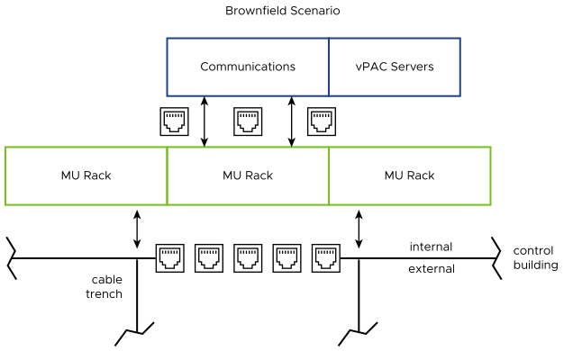
Locating MUs in a control building can offer simplicity in retrofitting within an existing site (brownfield scenario). If traditional secondary connections are utilized, these connections can be intercepted near their entry point into the enclosure. Limited real estate can be a concern, but as mentioned previously there is a net gain in free space achieved as the traditional PAC infrastructure is removed. The space gained can be used to offset the relatively small, grouped MU installations.
Initializing the Transformation
The preceding section shows how implementing software-defined substation application architecture can begin with singular power system elements, or in a fully-fledged substation build or retrofit. Therefore, deployments can be approached from within lifecycle planning, where power system element protection, automation, and controls are incorporated into the new solution piece-by-piece over a long period of time.
A more proactive and systematic approach can be taken to upgrade complete stations to establish similar architecture across the grid.