


This section details the Network Security Landscaping model.
Challenges with Traditional Security
The traditional security model assumes that all users and components in an organization's network can be trusted.
From the following figure:
The perimeter firewall blocks malicious traffic from the external network into the internal network.
If an attacker compromises a device, the attack spreads in the internal network.
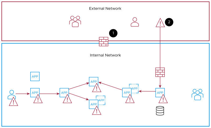
This method has remained almost the same for the last 30 years. It is typically built on static information:
A device joined the domain
The user has the correct password
Virtual Private Network (VPN) and multifactor authentication were introduced later to ensure external protection. But simply adding these additional types of authentication is not enough. This approach assumes that a user's identity is not compromised, and that all users act responsibly and can be trusted. This traditional, perimeter-centric security approach proves inadequate for protecting modern networked environments.
Zero-Trust Security Model
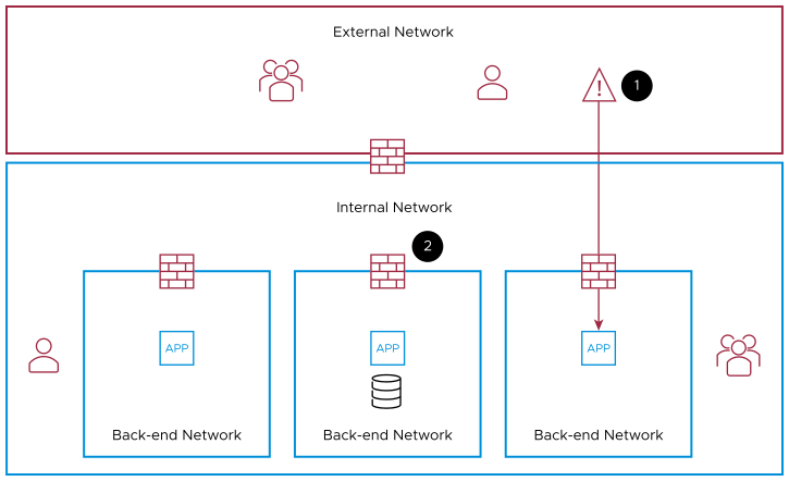
Zero-Trust, on the other hand, is a security model that does not automatically trust entities in the security perimeter.
From the following figure:
If an attacker compromises a device, the attack is contained within its perimeter.
In addition to the perimeter firewall, distributed internal firewalls are implemented to block lateral movement in the internal network.
This model emerged to mitigate the increase of network attacks and insider threats that exploit the breaches of a traditional perimeter-centric approach to security. The rapidly changing work styles and increased use of Software-as-a-Service (SaaS) applications resulted in Zero-Trust security becoming one of the most important forms of alternative security.
Zero-Trust moves the architecture from a single large DMZ to multiple smaller boundaries around each application and data. If an attacker succeeds in penetrating one of these boundaries, the attacker can only move in that perimeter and be easily contained. Notice how similar this appears when compared to the diagram discussed in the CIP-005 section of this document, in reference to an electronic security perimeter versus electronic access points.
Security Model
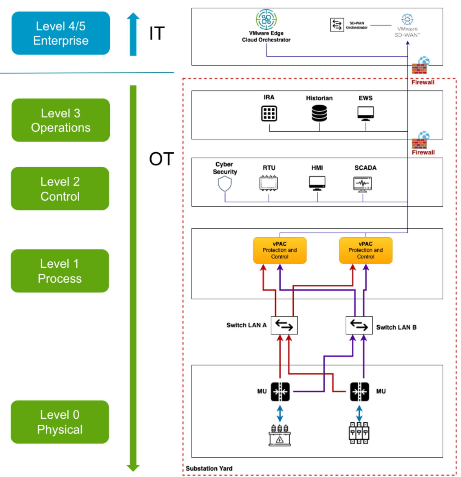
Level 4/5 : Control Site
These zones house the typical IT network, where the primary business functions occur, including the orchestration of substation operations. Enterprise resource planning (ERP) systems here drive plant production schedules, material use, shipping, and inventory levels.
Disruptions here can lead to prolonged downtime, with the potential for economic damage, failure of critical infrastructure, or revenue loss.
Level 3 : Substation Operations System Zone
This zone contains customized OT devices that manage production workflows in the substation.
DMZ: This zone includes security systems such as firewalls and proxies, used in an effort to prevent lateral threat movement between IT and OT. The rise of automation has increased the need for bidirectional data flows between OT and IT systems, so this IT-OT convergence layer can give organizations a competitive edge—but it can also increase their cyber risk if they adopt a flat network approach.
Level 2 : Control System Zone
- Supervisory control and data acquisition (SCADA) software oversees and controls physical processes, locally or remotely, and aggregates data to send to historians.
- Remote Terminal Unit (RTU) : A remote terminal unit (RTU) is a microprocessor-based electronic device used in industrial control systems (ICS) to connect various hardware to supervisory control and data acquisition (SCADA). RTUs are also referred to as remote telemetry units or remote telecontrol units.
- Human-machine interfaces (HMIs) connect to DCS and PLCs to allow for basic controls and monitoring.
Level 1 : Intelligent Devices Zone
This zone contains the instruments that send commands to the devices at level 0.
Protection Relays: Protection relays monitor electrical parameters, detecting faults like short circuits or overloads. They isolate faulty sections by tripping circuit breakers, safeguarding equipment and preventing system-wide damage. Coordination ensures selective tripping, while data logging enables analysis for system optimization and fault diagnosis. Overall, protection relays ensure power system stability, reliability, and asset protection.
Level 0 : Physical Process Zone
This zone contains sensors, circuit breakers or high voltage apparatus directly responsible for the distribution of the electricity. These devices communicate directly with the Merging Units which are responsible for converting the analog signals to the digital signals. Further the converted digital signals are sent over to IDE through the manageable switches.
