An HCX Service Mesh is the effective HCX services configuration for a paired source and a destination site. You can add a Service Mesh to a Site Pair that has a valid Compute Profile created on both of the sites.

Adding a Service Mesh initiates the deployment of HCX Interconnect virtual appliances on both of the sites. A Service Mesh is always created at the source site.

Prerequisites

Creating a Service Mesh requires:

  • A connected Site Pair.

  • A valid compute profile at the HCX Source HCX destination site.

  • For each switch that is present in the Compute Profile at both the source and the destination sites, the switch must span all hosts in at least one of the compute clusters. If the switch does not span all hosts in the compute cluster, then it is possible that the Network Extension appliance is deployed on a different host in a compute cluster and spans across a different switch. In this case, the Service Mesh deployment can fail.

Procedure

  1. Log in to the HCX Manager:
    https://hcx-ip-or-fqdn
  2. From the HCX Console, navigate to Interconnect > Multi-Site Service Mesh > Service Mesh.
    Created Service Mesh configurations are listed.
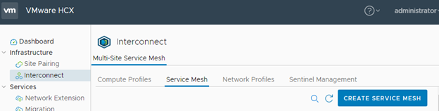
  3. Click Create Service Mesh:
    Shows the Create Service Mesh button highlighted in the HCX Manager Interconnect > Service Mesh screen.
  4. Select Sites:
    1. Click each drop-down and select a source and a destination site. Only connected Site Pairs are displayed.
    2. Click Continue.
  5. Select Compute Profiles:
    1. Click the Select Source Compute Profile drop-down and select a Compute Profile.
    2. Click the Select Remote Compute Profile drop-down and select a Compute Profile.
    3. Click Continue.
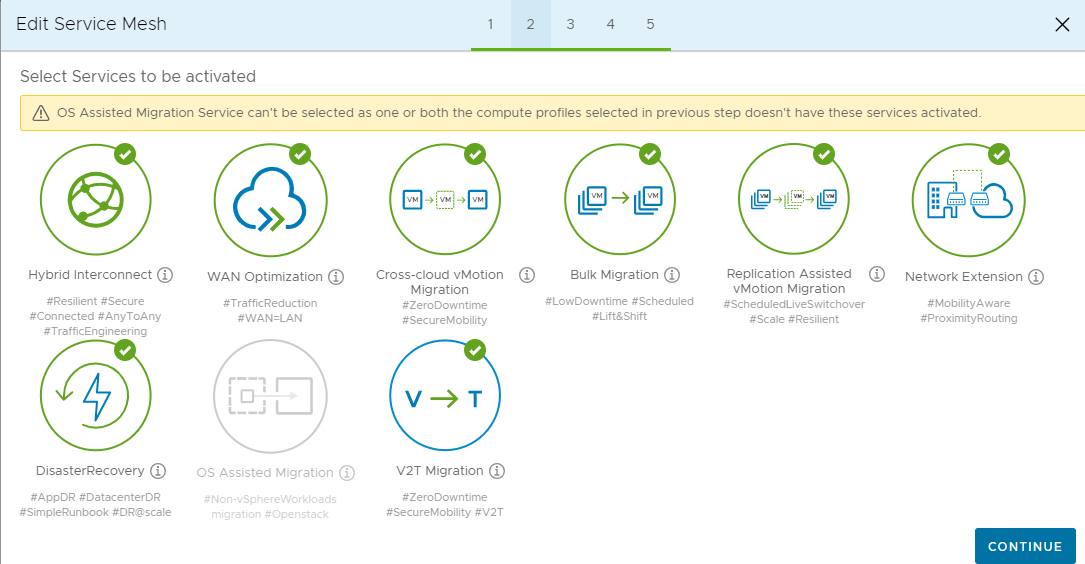
  6. Select the services to be activated, and click Continue.
    The HCX services available for activation are based on your selections in the source and remote site Compute Profiles, and based on the service entitlements for each site. In cases where the source and remote sites have been activated with different entitlements, the Service Mesh can inherit entitlements from either site. For more information, see Understanding Service Inheritance.

    List of services to enable with a unique icon for each service. Selected services display a green check mark.

  7. (Optional) Override the default Uplink Network Profile:

    By default, the HCX interconnect uses Uplink Network Profiles defined in the Compute Profile for the source and the destination sites. You can override the default.

    As an example, an override can be useful in Cloud Director-based deployments where an uplink network that deviates from a common configuration is created for an Organization to consume during the Service Mesh creation.

    1. Click the Select Source Uplink Network Profile drop-down.
    2. Select one or more networks. Click Close.

      The HCX Service Mesh can use up to three HCX Uplinks, adding network path failover and improving overall resiliency for HCX services. Multiple HCX Uplinks are not aggregated for increased throughput capacity. The following specific behaviors apply:

      • HCX attempts to load balance traffic on the Network Extension (HCX-NE) appliance based on characteristics of the flow and the performance of the uplinks.

      • HCX does not load balance migration traffic on the Interconnect (HCX-IX) appliance. Additional uplinks might or might not be used.

    3. Click Continue.
    4. Optionally, repeat these steps for the destination site.
  8. Configure the Network Extension appliances deployed per switch or Transport Zone:

    As an example, this advanced configuration can be useful when deploying Network Extension appliances to extend high volume source networks.

    1. In Advanced Configuration - Network Extension Appliance Scale Out, review the default Extension appliances per Network Container.
    2. For each entry, set the number of Network Extension appliances that HCX deploys when it activates the Service Mesh configuration.

      Extended network service can be carried by a single (standalone) Network Extension appliance at each site, or an HA group that consists of two Network Extension appliances at each site. For example, to create two standalone Network Extension appliances and one HA group for a container entry, set the scale-out number to 4 (2 + 1 x 2 = 4) in the Service Mesh.

      The default setting is 1. This setting restricts the Service Mesh to deploying one Network Extension appliance.

      Note:

      You must configure the Network Extension Appliance limit in the Compute Profile at both the source and remote sites to equal or exceed the number of scale-out appliances set in the Service Mesh.

      For the system resource considerations, see System Requirements.

    3. Click Continue.
  9. (Optional) Configure HCX Traffic Engineering features:
    1. To create multiple transport tunnels for directing the HCX traffic to a destination site, check Application Path Resiliency.

      Enabling Application Path Resiliency (APR) creates up to eight transport tunnels between each Interconnet and Network Extension appliance uplink interface IP address pair between sites. If a few tunnels fail, there is no impact in the data traffic as only one transport tunnel out of eight is used always to provide secure data transfer across the Wide Area Network (WAN) or Internet connection.

      Application Path Resiliency forwards traffic over one tunnel at a time and does not load balance across multiple paths.

      Note:

      To view the available tunnels after completing the Service Mesh configuration, navigate to Interconnect > Multi-Site Service Mesh > Service Mesh > View Appliances and expand the HCX-WAN-IX appliance.

      Important: For additional dynamic tunnel requirement, the source Interconnect (IX) and Network Extension (NE) appliances uses a random source UDP port in the 4500 – 4628 range and target UDP port as 4500 to create a different flow for each subsequent tunnel. The reverse tunnel originated by target IX/NE appliances have source port as UDP 4500 and destination ports from same random ports used by source appliances for the forward direction in the range 4500 – 4628.

      Ensure the firewall settings on either side allow for that connectivity.

    2. To dynamically manage the TCP segment size and optimize the transport performance for the HCX Network Extension service traffic, check TCP Flow Conditioning.

      This option is available only after activating the HCX Network Extension service.

    3. To manage the bandwidth consumed for migrations across all uplink networks, use the up and down arrows to change the bandwidth setting.

      This option is available only after activating the HCX WAN Optimization service.

      Note:

      It is a best practice to retain the default setting of 10000 Mb/S.

  10. Review Topology Preview:
    1. Review the selected clusters and the resources.
    2. Click Continue.
  11. Ready to Complete:
    1. To view a summary of the Service Mesh selections, click the here link.
    2. Name the Service Mesh.
      The Service Mesh name has a limit of 50 characters.
    3. To create the service mesh, click Finish.
    After the Service Mesh configuration is complete, verify the underlay network performance for each Uplink Network. The underlay network performance must meet the minimum requirements for HCX services. See Understanding HCX Transport Analytics.

What to do next

If it is necessary to make any direct changes to an existing Service Mesh, such as activating or deactivating services and overriding uplinks, select Interconnect > Service Mesh > Edit. The editing workflow includes a preview screen, listing the changes and describing the impact of those changes on related services prior to finishing the procedure. You can select to complete or cancel the update.