


The insurance company designs a Cloud Pod Architecture topology that includes a site for each region.
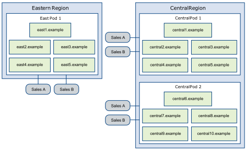
In this topology, the Eastern region site contains a single pod, East Pod 1, that consists of five Connection Server instances called east1.example through east5.example.
The Central region site contains two pods, Central Pod 1 and Central Pod 2. Each pod contains five Connection Server instances. The Connection Servers in the first pod are called central1.example through central5.example. The Connection Server instances in the second pod are called central6.example through central10.example.
Each pod in the topology contains two desktop pools of sales agent desktops, called Sales A and Sales B.
