The NSX Advanced Load Balancer application provides several benefits to an application. To extend the benefits to a network firewall, the firewalls are sandwiched between the load balancers (SEs). This solution can be deployed using Load Balancers in many variants. This is possible using the Wildcard VIP functionality and Routing Auto Gateway.
Topology
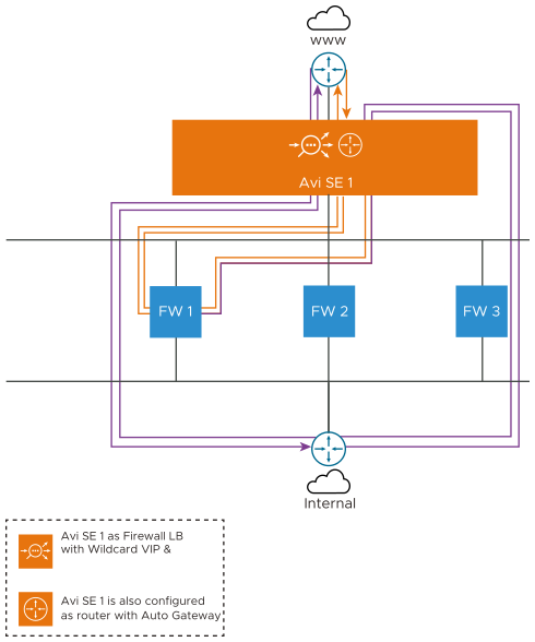
A common firewall sandwich topology is as shown below:
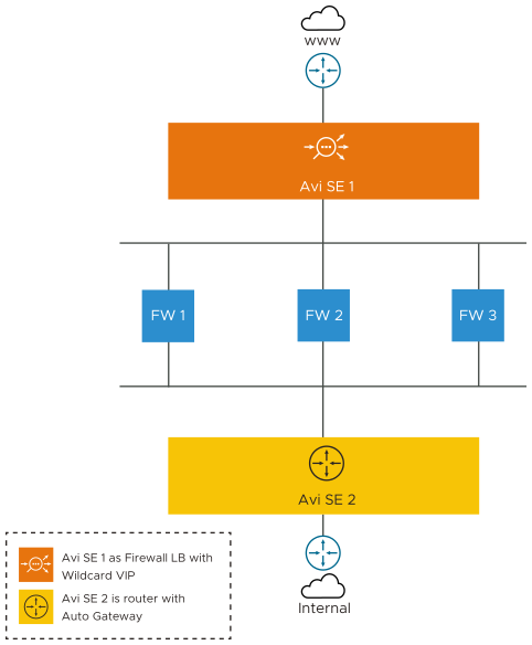
In the above image,
The SE 1 is acting as a Load Balancer deployed with Wildcard VIP and SE 2 is acting as a router configured with routing auto gateway enabled. Also, SE 1 and SE 2 are the Active SEs of different SE Groups deployed in legacy HA mode.
The SE1 is deployed with the wildcard VIP and the traffic gets load balanced to the firewalls. As firewalls expect the client traffic unchanged for validation, the application profile of the wildcard virtual service has to be configured with preserve_client_ip, preserve_client_port, preserve_destination_ip_port.
Basic Traffic Flow through Firewall Sandwich
The basic traffic flow from the internet world (www) to the internal server of corporate network is explained below.
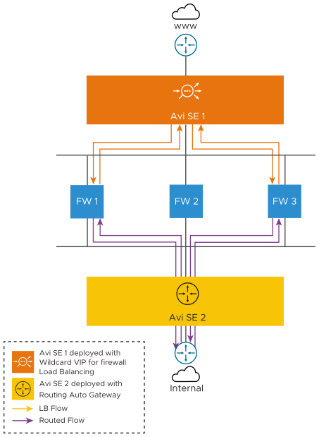
The traffic flow through the firewall sandwich topology deployed is as explained below:
The SE 1 is introduced ahead of the firewalls for load-balancing the traffic across the firewalls. The orange flow in the image above indicates the Load balancing of the client traffic to firewall.
The traffic that gets through the firewall policies, is now propagated to SE 2.
From SE 2, as we enabled the routing with auto gateway functionality, the traffic is routed to the internal network remembering the Firewall1. The purple flow indicates the routing traffic.
The traffic from the internal network passes through SE 2, which acts as a router. SE 2 has the auto gateway functionality that ensures the traffic is redirected to the firewall it was propagated from.
The firewall redirects the same traffic to SE 1.
From SE 1, the traffic goes outbound through the corporate network.
The firewall sandwich topology improves the:
Availability of the firewalls
Scalability of the firewall traffic
Manageability during failover or maintenance
Use Cases
Many combinations of the firewall sandwich model can be derived from the configuration of Wildcard VIP and Routing Auto gateway. These are some use cases of the firewall sandwich topology that could be deployed using wildcard VIP and auto gateway functionality:
Deployment Scenario 1
The client can configure the wildcard VIP on SE 1 to load balance only 40 percent of the traffic to the FW. 60 percent of the remaining traffic is directly routed to the SE-2, where with the auto gateway functionality, routes the traffic to the SE 1, which then reaches the client.
Note:The SE-1 and SE-2 are active SEs of different SE groups deployed in legacy HA mode.
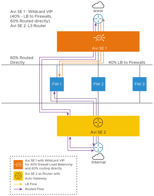
In this use case, a sample of the traffic is inspected by the firewall and the remaining is considered as the trusted traffic and is directly routed to the internal network.
Deployment Scenario 2
The SE-1 is deployed as the wildcard virtual service load balancer and SE-2 is the application load balancer.
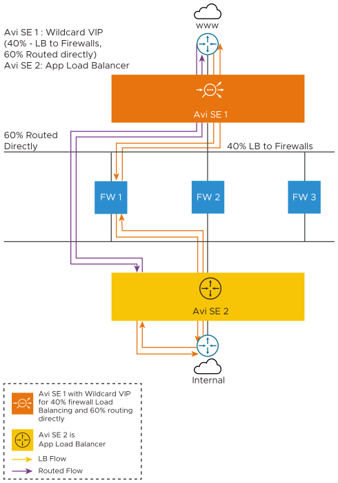
The SE 1 acts as the network load balancer with wildcard VIP installed. The SE1 selects one FW and forwards the traffic to the FW, and from there, the traffic is sent to the SE 2, which is the application load balancer.
The application virtual service picks the traffic and load balances it into the internal network.
When the SE receives the response from the application server, it propagates the traffic to the same FW that it came from.
The traffic then reaches the SE 1 and further reaches the client.
60 percent of the traffic moves from SE 1 to the SE 2 directly. It gets load balanced here and is redirected to SE 1. It then gets propagated to the client.
Open Firewall Sandwich Topology
This topology is also called Firewall on a Stick. In this topology, a single SE 1 is hosting a wildcard VIP and also acting as a router. Here, the SE has a three-arm set up:
One arm is connected to the internet (interface 1)
One arm is connected to FW 1, FW 2, and FW 3 (interface 2)
One arm is connected to the internal network (interface 3)
Traffic from the North reaches interface 1 of the SE. It matches the wildcard virtual service and selects one of the FWs. The SE acts as a default gateway for the FW. The same traffic is forwarded to the SE from the FW. The wildcard VIP is placed only on interface 1. So, the traffic is forwarded as the routing flow to the internal network.
When the traffic returns, the flow entries match and the traffic is returned to the same FW from which it was propagated. From FW 1, the traffic flows to the client, based on the reverse flow entry that is installed as a part of the wildcard VIP.
The wildcard VIP can have different services as a *, 80 and *, 8080. If traffic matches with *, 8080, the traffic is transparently forwarded to the internal network and the return traffic is directly routed to the client.
A portion of the traffic gets matched with the wildcard VIP and gets load balanced to the internal network. The traffic that does not match the wildcard VIP is part of the routing flow.
Firewall Sandwich Topology in Detail
In this topology, the SE 1 of Tier 1 SE group has the wildcard VIP configured. SE 2 of Tier 2 SE group is deployed as the L3 router with auto gateway functionality. The wildcard VIP and the auto gateway functionality are configured as shown below:
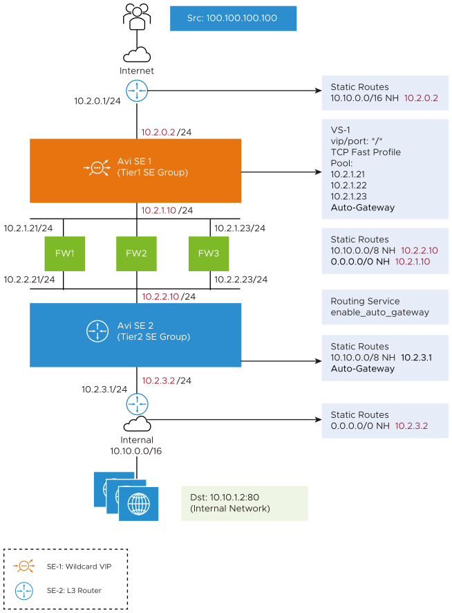
In VS-1 / is configured as the wildcard VIP and FW 1, FW 2, and FW 3 are configured as pool members. This is the network configuration in every element of this sandwich topology.
Traffic flow from the Internet to the Internal Servers in the Firewall Sandwich
The client initiates the traffic to the server from 10.10.1.2. The traffic traverses from North to South and is detailed below with the sample flow entries as shown in the image:
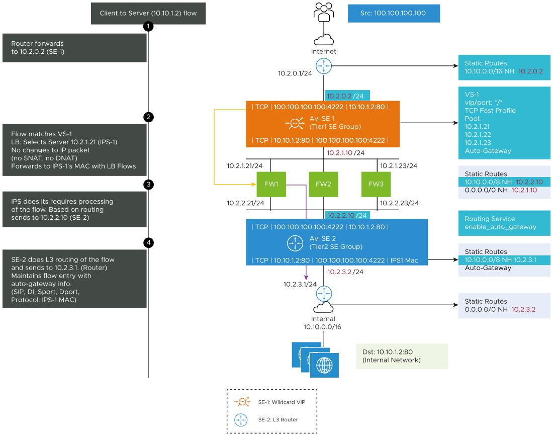
Step 1: The traffic reaches SE 1 and matches the static route. As it is the internal network, the next hop is 10.2.0.2 which is the floating interface IP of SE 1.
Step 2: The traffic in SE 1 matches with VS-1 (/). The flow matches the wildcard VS-1 and it selects FW-1 and transparently forwards the traffic to FW 1 without SNAT or DNAT.
Step 3: FW 1 delivers this packet to SE 2 based on the routes configured in the FW layer.
Step 4: The SE 2 is deployed as an L3 router with auto gateway functionality. The traffic matches the routing service with enable_auto_gateway functionality. It installs the flow entries in SE.
The FW 1 MAC gets cached in the backend flow entry. This will be used in the return path. The traffic in the return direction has to go through the same FW from where it came from.
Return Traffic flow from the Internal Servers to the Internet in the Firewall Sandwich
The traffic flow from server to client is as shown below:
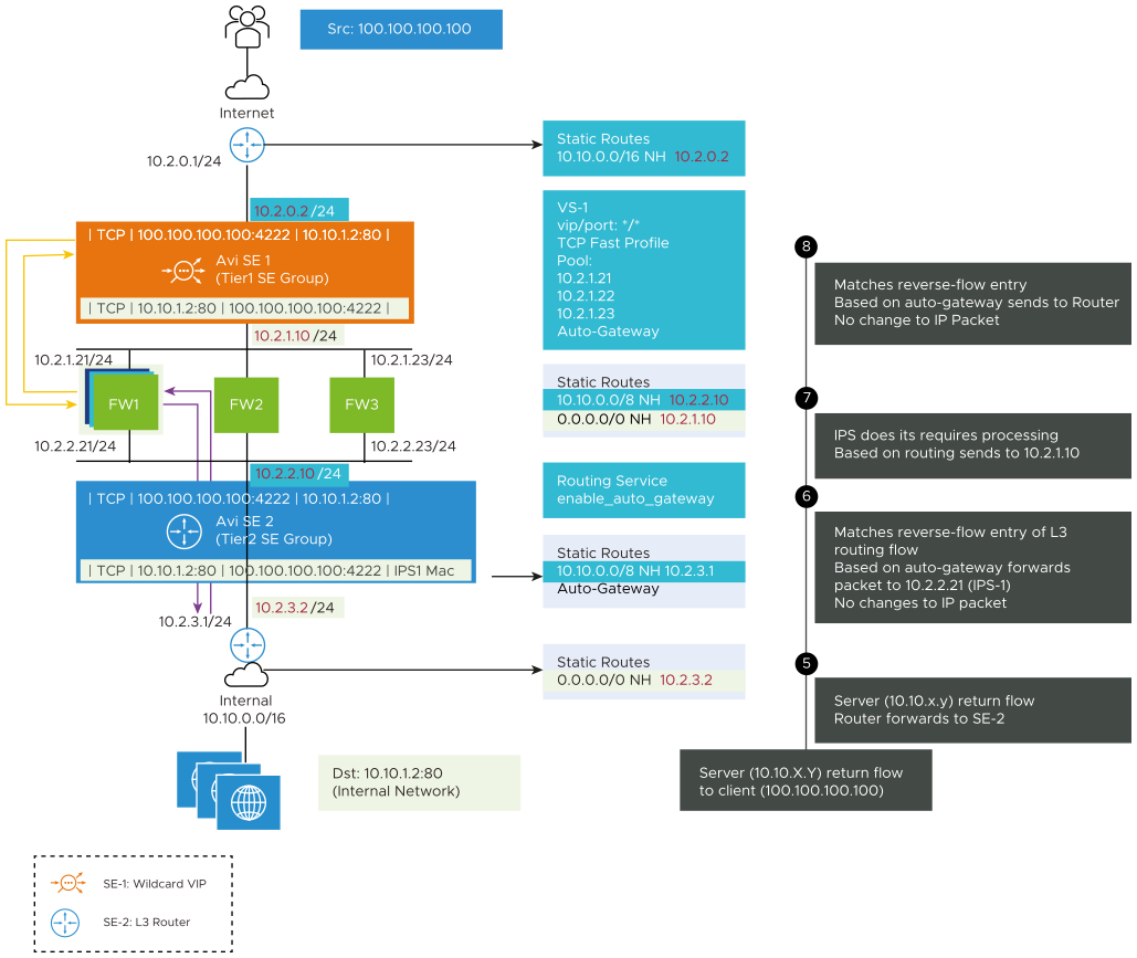
Step 5: The traffic reaches SE 2 as it is configured as the default gateway.
Step 6: SE 2 is the default gateway. When the traffic reaches SE 2, it matches the reverse-flow entry and then forwards that traffic to FW 1 based on the cached auto gateway Mac.
Step 7: FW 1 will return the traffic to SE 1.
Step 8: The reverse-flow entry of the wildcard is matched and matches the reverse flow entry of wildcard VS in the load balancing flow and traffic returns to the client.