


This topic gives steps for creating VRF contexts on the Service Engine Group, moving port groups to the VRF contexts, and creating virtual services in those contexts.
This section assumes that the Controller has already been installed and that the initial configuration of the Controller has been performed using the setup wizard.
The NSX Advanced Load Balancer user must have write privileges for the admin tenant. These steps can be performed only from the admin tenant.
Creating Networks to the VRF Contexts
To create networks to the VRF contexts, navigate to .
Select cloud by clicking the Select Cloud drop-down menu. Click CREATE.
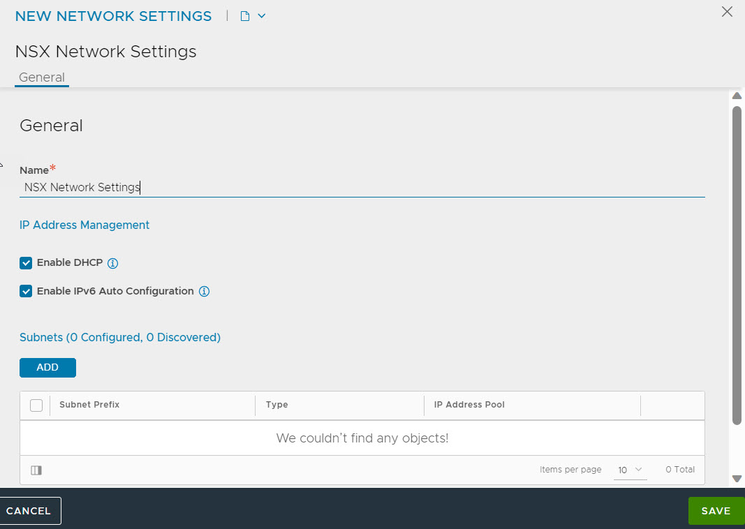
Specify the name. Select the Enable DHCP check box to select the IP address management scheme for this network.
Note:Enable DHCP and Enable IPv6 Auto Configuration fields are enabled by default for all newly created clouds.
Click SAVE.
Creating VRF Contexts
Virtual routing and forwarding (VRF) IP technology allows to configure multiple routing table instances to simultaneously co-exist within the same router. VRF contexts in NSX Advanced Load Balancer enable the assignment of NSX Advanced Load Balancer Service Engine data interfaces to multiple VRFs. The NSX Advanced Load Balancer platform helps each VRF network achieve the target level of performance and increases network security.
By default, NSX Advanced Load Balancer has the global VRF context created. The following are the steps to create VRF contexts:
Navigate to .
Click CREATE to open the CREATE VRF CONTEXT screen.
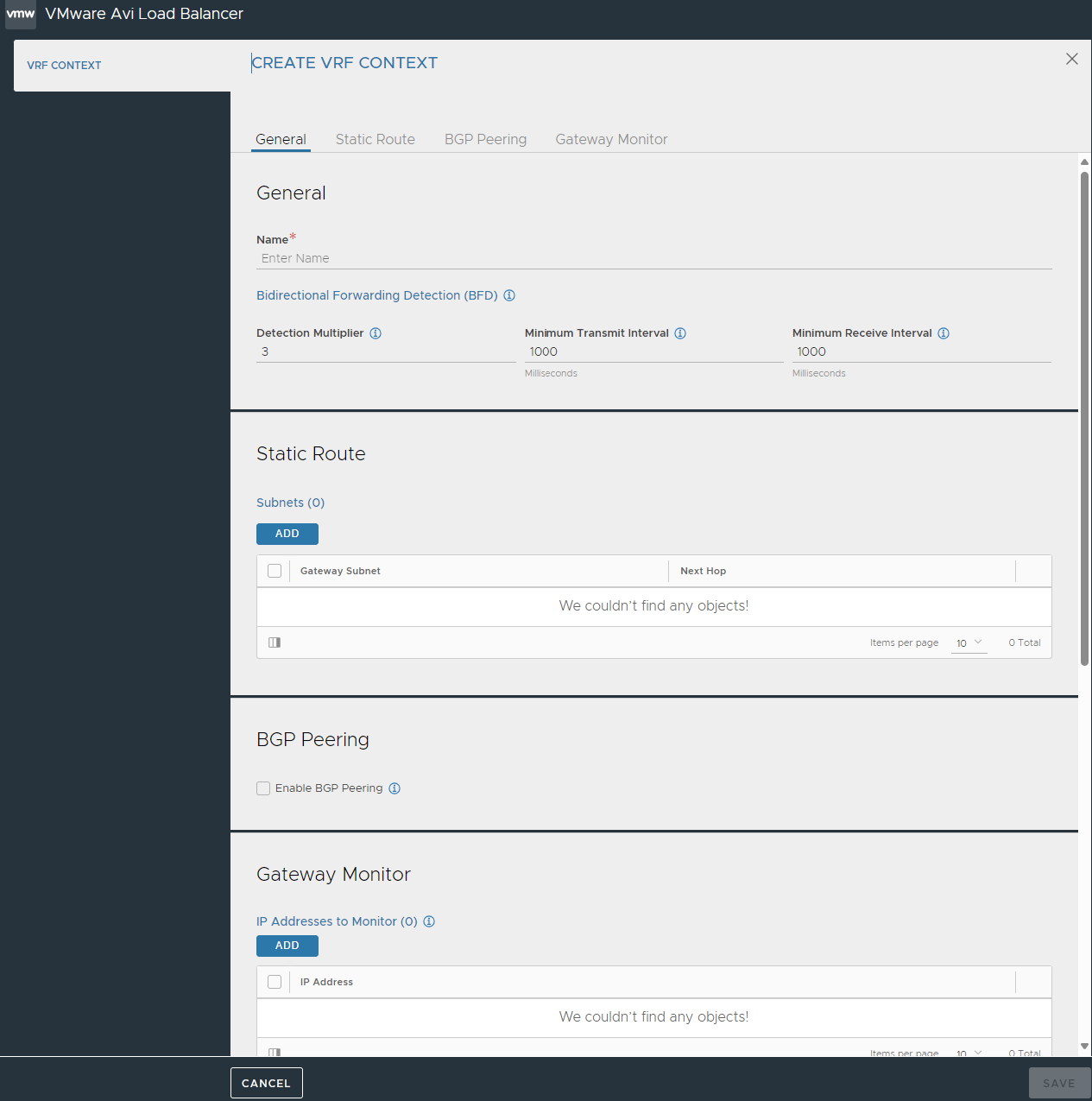
Specify the Name for the VRF context.
Configure Bidirectional Forwarding Detection (BFD) to enable networking peers on each end of a link to quickly detect and recover from a link failure.
Specify Detection Multiplier to be used for BFD.
Specify the minimum rate at which the packets are sent (in milliseconds) in the Minimum Transmit Interval field.
Specify the minimum rate at which the packets are received (in milliseconds) in the Minimum Receive Interval field.
Click ADD to configure Static Route.
Specify theGateway Subnet and the Next Hop for any traffic matching the IP subnet to be sent to the IP address of the next hop gateway.
To configure more hops, click ADD.
Select Enable BGP Peering checkbox to configure BGP local and peer details.
BGP Autonomous System (AS) ID: Specify the local autonomous system ID.
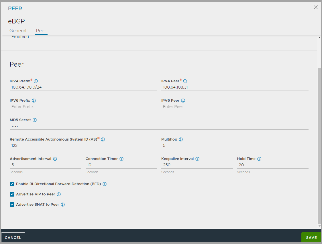
Type: Select the BGP peer type from the drop-down menu. The followinfg are the options available:
iBGP
eBGP
Keepalive Interval: Specify keepalive interval for peers.
Hold Time: Specify the hold time for peers.
Local Preference: Specify the local preference to be used for routes advertised. This is applicable only over iBGP.
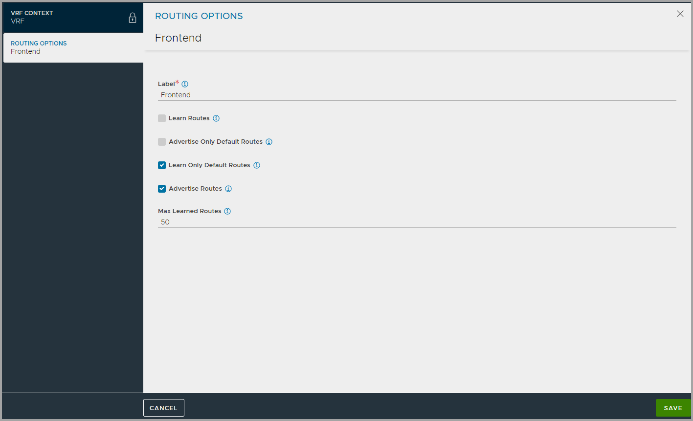
Under Routing Options click ADD to configure learning and advertising options for BGP Peers.
Under Peers, click ADD and configure the required settings.
Click ADD under Community Strings and specify either in aa:nn format where aa, nn is within [1,65535] or local-AS|no-advertise|no-export|internet format.
Specify IP Address to monitor in Gateway Monitor tab.
Click SAVE.
Creating Virtual Services in a VRF
Navigate to and click CREATE VIRTUAL SERVICE.
Select the VRF context from the list, and click Next.
Specify a name for the virtual service.
Specify the Virtual IP address (VIP) on which NSX Advanced Load Balancer will listen for requests to the virtual service.
In Select Servers by Network section, select the network to place the virtual service. The list displays only the networks within the selected VRF context.
Note:The Select Servers by Network button is available if VMware cloud is configured in read-access or write-access mode. In no-access mode, it is not available.
After a network is selected, a list of the servers in that network appears.
Click to select individual servers and click ADD SERVERS.
Click Save.
Note:The steps to create a virtual service in a VRF can be performed from the admin tenant or from another tenant.
