Border Gateway Protocol (BGP) makes core routing decisions. It includes a table of IP networks or prefixes, which designate network reachability among multiple autonomous systems.
Procedure
- Log in to the vSphere Web Client.
- Click .
- Double-click an NSX Edge.
- Click .
- Next to BGP Configuration, click Edit, and then click Enable BGP.
- (Optional) Click Enable Graceful Restart for packet forwarding to be uninterrupted during restart of BGP services.
- (Optional) Click Enable Default Originate to allow the ESG to advertise itself as a default gateway to its peers.
- In Local AS, enter the router ID. The routes are advertised when BGP peers with routers in other autonomous systems (AS). The path of autonomous systems that a route traverses is used as one metric when selecting the best path to a destination.
- In Neighbors, click Add.
- Specify basic details of the BGP neighbor.
- Type the IP address of the neighbor.
When you configure BGP peering between an edge services gateway (ESG) and a logical router, use the protocol IP address of the logical router as the BGP neighbor address of the ESG.
- (On a logical router only) Type the forwarding address.
The forwarding address is the IP address that you assigned to the distributed logical router's interface facing its BGP neighbor (its uplink interface).
- (On a logical router only) Type the protocol address.
The protocol address is the IP address that the logical router uses to form a BGP neighbor relationship. It can be any IP address in the same subnet as the forwarding address, but this IP address must not be used anywhere else. When you configure BGP peering between an edge services gateway (ESG) and a logical router, use the protocol IP address of the logical router as the BGP neighbor IP address of the ESG.
- Type the remote AS.
- (Optional) Disable Remove Private AS. By default, it is enabled.
- Edit the default weight for the neighbor connection, if necessary. The default weight is 60.
- Hold Down Timer displays a default value of 180 seconds, which is three times the value of keep alive timer. Edit if necessary.
When BGP peering is achieved between two neighbors, the NSX Edge starts a hold down timer. Each keep alive message it receives from the neighbor resets the hold down timer to 0. When the NSX Edge fails to receive three consecutive keep alive messages so that the hold down timer reaches 180 seconds, the NSX Edge considers the neighbor as down and deletes the routes from this neighbor.Note: The default time-to-live (TTL) value for eBGP neighbors is 1 and for iBGP neighbors is 64. This value cannot be modified.
- Keep Alive Timer displays the default frequency of 60 seconds at which a BGP neighbor sends keep alive messages to its peer. Edit if necessary.
- If authentication is required, enter an authentication password.
Password must be at least 12 characters and it must satisfy these rules:
- Must not exceed 255 characters
- At least one uppercase letter and one lowercase letter
- At least one number
- At least one special character
- Must not contain the user name as a substring
- Must not consecutively repeat a character 3 or more times.
Each segment sent on the connection between the neighbors is verified. MD5 authentication must be configured with the same password on both BGP neighbors, otherwise, the connection between them is not made. You cannot enter a password when FIPS mode is enabled.
- Type the IP address of the neighbor.
- Specify the BGP Filters.
- Click Add.
Caution: A "block all" rule is enforced at the end of the filters.
- Select the direction to indicate whether you are filtering traffic to or from the neighbor.
- Select the action to indicate whether you are allowing or denying traffic.
- Type the network in CIDR format that you want to filter to or from the neighbor.
- Type the IP prefixes that are to be filtered and click OK.
- Click Add.
- Click Publish Changes.
Example: Configure BGP Between an ESG and a Logical (Distributed) Router

In this topology, the ESG is in AS 64511. The logical router (DLR) is in AS 64512.
The forwarding address of the logical router is 192.168.10.2. This address is configured on the uplink interface of the logical router. The protocol address of the logical router is 192.168.10.3. The ESG uses this address to form a BGP peer relationship with the logical router.
- Local AS: 64512
- Neighbor settings:
- Forwarding address: 192.168.10.2
- Protocol address: 192.168.10.3
- IP address: 192.168.10.1
- Remote AS: 64511
- Local AS: 64511
- Neighbor settings:
- IP address: 192.168.10.3. This IP address is the protocol address of the logical router.
- Remote AS: 64512
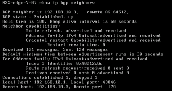
On the logical router, run the show ip bgp neighbors command, and make sure that the BGP state is Established.

On the ESG, run the show ip bgp neighbors command, and make sure that the BGP state is Established.