Configuring OSPF on a logical router enables VM connectivity across logical routers and from logical routers to edge services gateways (ESGs).

OSPF routing policies provide a dynamic process of traffic load balancing between routes of equal cost.

An OSPF network is divided into routing areas to optimize traffic flow and limit the size of routing tables. An area is a logical collection of OSPF networks, routers, and links that have the same area identification.

Areas are identified by an Area ID.

Prerequisites

A Router ID must be configured, as shown in OSPF Configured on the Logical (Distributed) Router.

When you enable a router ID, the text box is populated by default with the uplink interface of the logical router.

Procedure

  1. Log in to the vSphere Web Client.
  2. Click Networking & Security > NSX Edges.
  3. Double-click a logical router.
  4. Click Manage > Routing > OSPF.
  5. Enable OSPF.
    1. Next to OSPF Configuration, click Edit, and then click Enable OSPF
    2. In Forwarding Address, type an IP address that is to be used by the router datapath module in the hosts to forward datapath packets.
    3. In Protocol Address, type a unique IP address within the same subnet as the Forwarding Address. The protocol address is used by the protocol to form adjacencies with the peers.
    4. (Optional) Enable Graceful Restart for packet forwarding to be uninterrupted during restart of OSPF Services.
  6. Configure the OSPF areas.
    1. (Optional) Delete the not-so-stubby area (NSSA) 51 that is configured by default.
    2. In Area Definitions, click Add.
    3. Type an Area ID. NSX Edge supports an area ID in the form of a decimal number. Valid values are 0–4294967295.
    4. In Type, select Normal or NSSA.
      NSSAs prevent the flooding of AS-external link-state advertisements (LSAs) into NSSAs. They rely on default routing to external destinations. Hence, NSSAs must be placed at the edge of an OSPF routing domain. NSSA can import external routes into the OSPF routing domain, thereby providing transit service to small routing domains that are not part of the OSPF routing domain.
  7. (Optional) Select the type of Authentication. OSPF performs authentication at the area level.
    All routers within the area must have the same authentication and corresponding password configured. For MD5 authentication to work, both the receiving and transmitting routers must have the same MD5 key.
    1. None: No authentication is required, which is the default value.
    2. Password: In this method of authentication, a password is included in the transmitted packet.
    3. MD5: This authentication method uses MD5 (Message Digest type 5 ) encryption. An MD5 checksum is included in the transmitted packet.
    4. For Password or MD5 type authentication, type the password or MD5 key.
      Important:
      • If NSX Edge is configured for HA with OSPF graceful restart enabled and MD5 is used for authentication, OSPF fails to restart gracefully. Adjacencies are formed only after the grace period expires on the OSPF helper nodes.
      • You cannot configure MD5 authentication when FIPS mode is enabled.
      • NSX Data Center for vSphere always uses a key ID value of 1. Any device not managed by NSX Data Center for vSphere that peers with an Edge Services Gateway or Logical Distributed Router must be configured to use a key ID of value 1 when MD5 authentication is used. Otherwise an OSPF session cannot be established.
  8. Map interfaces to the areas.
    1. In Area to Interface Mapping, click Add to map the interface that belongs to the OSPF area.
    2. Select the interface that you want to map and the OSPF area that you want to map it to.
  9. (Optional) Edit the default OSPF settings.
    In most cases, it is recommended to retain the default OSPF settings. If you do change the settings, make sure that the OSPF peers use the same settings.
    1. Hello Interval displays the default interval between hello packets that are sent on the interface.
    2. Dead Interval displays the default interval during which at least one hello packet must be received from a neighbor before the router declares that neighbor down.
    3. Priority displays the default priority of the interface. The interface with the highest priority is the designated router.
    4. Cost of an interface displays the default overhead required to send packets across that interface. The cost of an interface is inversely proportional to the bandwidth of that interface. The larger the bandwidth, the smaller the cost.
  10. Click Publish Changes.

Example: OSPF Configured on the Logical (Distributed) Router

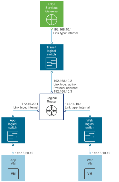
One simple NSX scenario that uses OSPF is when a logical router (DLR) and an edge services gateway (ESG) are OSPF neighbors, as shown here.

Figure 1. NSX Data Center for vSphere Topology
The image is described in the surrounding text.
On the Global Configuration page, the configuration settings are as follows:
  • Gateway IP: 192.168.10.1. The logical router's default gateway is the ESG's internal interface IP address (192.168.10.1).
  • Router ID: 192.168.10.2. The router ID is the uplink interface of the logical router. In other words, the IP address that faces the ESG.
On the OSPF Configuration page, the configuration settings are as follows:
  • Forwarding Address: 192.168.10.2
  • Protocol Address: 192.168.10.3. The protocol address can be any IP address that is in the same subnet and is not used anywhere else. In this case, 192.168.10.3 is configured.
  • Area Definition:
    • Area ID: 0
    • Type: Normal
    • Authentication: None
The uplink interface (the interface facing the ESG) is mapped to the area, as follows:
  • Interface: To-ESG
  • Area ID: 0
  • Hello Interval (seconds): 10
  • Dear Interval (seconds): 40
  • Priority: 128
  • Cost: 1

What to do next

Make sure the route redistribution and firewall configuration allow the correct routes to be advertised.

In this example, the logical router's connected routes (172.16.10.0/24 and 172.16.20.0/24) are advertised into OSPF. To verify the redistributed routes, on the left navigation panel, click Route Redistribution, and check the following settings:
  • Route Redistribution Status shows that OSPF is enabled.
  • Route Redistribution Table shows the following:
    • Learner: OSPF
    • From: Connected
    • Prefix: Any
    • Action: Permit
If you enabled SSH when you created the logical router, you must also configure a firewall filter that allows SSH to the logical router's protocol address. For example, you can create a firewall filter rule with the following settings:
  • Name: ssh
  • Type: User
  • Source: Any
  • Destination: Protocol address with value: 192.168.10.3
  • Service: SSH