


Company ACME Enterprise has two private data center sites in the US, one at Palo Alto, and the other at Austin. During a scheduled maintenance or an unforeseen failure at the Palo Alto site, the company recovers all the applications at its Austin site.
- Remapping IP address
- Synchronizing security policies
- Updating other services that use the application IP addresses, such as DNS, security policies, and other services.
This traditional approach to a disaster recovery consumes significant additional time to complete 100% recovery at its site in Austin. To achieve a fast disaster recovery with a minimal downtime, ACME Enterprise decides to deploy NSX Data Center 6.4.5 or later in a Cross-vCenter environment, as shown in the following logical topology diagram.
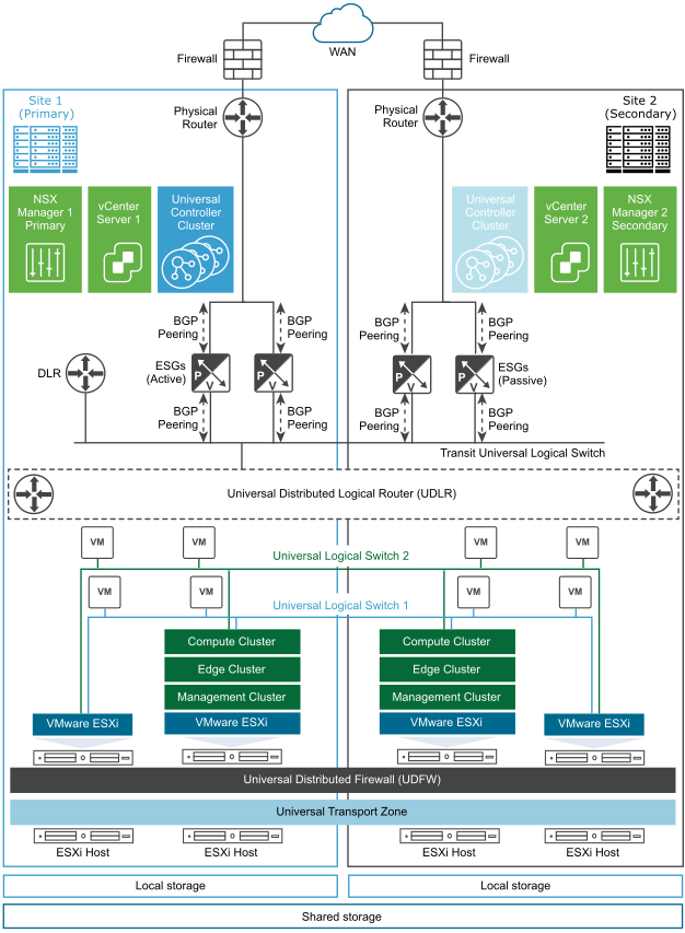
In this topology, site 1 at Palo Alto is the primary (protected) data center, and site 2 at Austin is the secondary (recovery) data center. Each site has a single vCenter Server, which is paired with its own NSX Manager. The NSX Manager at site 1 (Palo Alto) is assigned the role of a primary NSX Manager, and the NSX Manager at site 2 (Austin) is assigned the role of a secondary NSX Manager.
ACME Enterprise deploys the Cross-vCenter NSX across both sites in an Active - Passive mode. 100% applications (workloads) run on site 1 at Palo Alto, and 0% applications run on site 2 at Austin. That is, by default, site 2 is in passive or standby mode.
Both sites have their own Compute, Edge, and Management Clusters and ESGs that are local to that site. As local egress is disabled on the UDLR, only a single UDLR Control VM is deployed on the primary site. The UDLR Control VM is connected to the universal transit logical switch.
The NSX administrator creates universal objects that span two vCenter domains at site 1 and site 2. The universal logical networks use universal networking and security objects, such as Universal Logical Switches (ULS), Universal Distributed Logical Routers (UDLR), and Universal Distributed Firewall (UDFW).
- Creates a universal transport zone from the primary NSX Manager.
- Deploys a Universal Controller Cluster with three controller nodes.
- Adds the local Compute, Edge, and Management clusters to the universal transport zone from the primary NSX Manager.
- Disables local egress, enables ECMP, and enables Graceful Restart on the UDLR Control VM (Edge Appliance VM).
- Configures dynamic routing using BGP between the Edge Services Gateways (ESGs) and the UDLR Control VM.
- Disables ECMP and enables Graceful Restart on both the ESGs.
- Disables firewall on both the ESGs because ECMP is enabled on the UDLR Control VM and to ensure that all traffic is allowed.
The following diagram shows a sample configuration of the uplink and downlink interfaces on the ESGs and the UDLRs at site 1.

- Adds the local Compute, Edge, and Management clusters to the universal transport zone from the secondary NSX Manager.
- Specifies similar downlink interfaces on the ESGs as configured at site 1 ESGs.
- Specifies similar BGP configuration on the ESGs as configured at site 1 ESGs.
- Powers down the ESGs on the secondary site when site 1 is active.
- Scenario 1: Scheduled full site failure at site 1
- Scenario 2: Unscheduled full site failure at site 1
- Scenario 3: Full failback to site 1
