Hardware gateway configuration maps physical networks to virtual networks. The mapping configuration allows NSX to leverage the Open vSwitch Database (OVSDB).
The OVSDB database contains information about the physical hardware and the virtual network. The vendor hardware hosts the database server.
The hardware gateway switches in the NSX logical networks terminate VXLAN tunnels. To the virtual network, the hardware gateway switches are known as hardware VTEP. For more information about VTEPs, see the NSX Installation guide and NSX Network Virtualization Design guide.
A minimal topology with a hardware gateway includes the following components:
- Physical server
- Hardware gateway switch (L2 port)
- IP network
- Hypervisors a minimum of four, including two replication clusters with VMs
- Controller cluster with at least three nodes
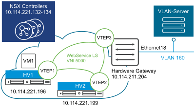
The sample topology with a hardware gateway shows HV1 and HV2 as the two hypervisors. The VM1 virtual machine is on HV1. VTEP1 is on HV1, VTEP2 is on HV2, and VTEP3 is on the hardware gateway. The hardware gateway is located in a different subnet 211 compared to the two hypervisors that are located in the same subnet 221.

The hardware gateway underlying configuration can have any one of the following components:
- Single switch
- Multiple physical bus switches with different IP addresses
- Hardware switch controller with multiple switches
The NSX Controller communicates with the hardware gateway using its IP address on port 6640. This connection is used to send and receive OVSDB transactions from hardware gateways.