Configuring OSPF on an edge services gateway (ESG) enables the ESG to learn and advertise routes. The most common application of OSPF on an ESG is on the link between the ESG and a Logical (Distributed) Router. This allows the ESG to learn about the logical interfaces (LIFS) that are connected to the logical router. This goal can be accomplished with OSPF, IS-IS, BGP or static routing.
OSPF routing policies provide a dynamic process of traffic load balancing between routes of equal cost.
An OSPF network is divided into routing areas to optimize traffic flow and limit the size of routing tables. An area is a logical collection of OSPF networks, routers, and links that have the same area identification.
When you enable a router ID, the text box is populated by default with the ESG's uplink interface IP address.
Procedure
Log in to the vSphere Web Client.
Click Networking & Security > NSX Edges.
Double-click an ESG.
Click Manage > Routing > OSPF.
Enable OSPF.
Next to OSPF Configuration, click Edit, and then click Enable OSPF
(Optional) Click Enable Graceful Restart for packet forwarding to be uninterrupted during restart of OSPF services.
(Optional) Click Enable Default Originate to allow the ESG to advertise itself as a default gateway to its peers.
Configure the OSPF areas.
(Optional) Delete the not-so-stubby area (NSSA) 51 that is configured by default.
In Area Definitions, click Add.
Enter an Area ID. NSX Edge supports an area ID in the form of a decimal number. Valid values are 0–4294967295.
In Type, select Normal or NSSA.
NSSAs prevent the flooding of AS-external link-state advertisements (LSAs) into NSSAs. They rely on default routing to external destinations. Hence, NSSAs must be placed at the edge of an OSPF routing domain. NSSA can import external routes into the OSPF routing domain, providing transit service to small routing domains that are not part of the OSPF routing domain.
(Optional) When you select the NSSA area type, the NSSA Translator Role appears. Select the Always check box to translate Type-7 LSAs to Type-5 LSAs. All Type-7 LSAs are translated into Type-5 LSAs by the NSSA.
(Optional) Select the type of Authentication. OSPF performs authentication at the area level.
All routers within the area must have the same authentication and corresponding password configured. For MD5 authentication to work, both the receiving and transmitting routers must have the same MD5 key.
None: No authentication is required, which is the default value.
Password: In this method of authentication, a password is included in the transmitted packet.
MD5: This authentication method uses MD5 (Message Digest type 5 ) encryption. An MD5 checksum is included in the transmitted packet.
For Password or MD5 type authentication, enter the password or MD5 key.
Important:
If NSX Edge is configured for HA with OSPF graceful restart enabled and MD5 is used for authentication, OSPF fails to restart gracefully. Adjacencies are formed only after the grace period expires on the OSPF helper nodes.
You cannot configure MD5 authentication when FIPS mode is enabled.
NSX Data Center for vSphere always uses a key ID value of 1. Any device not managed by NSX Data Center for vSphere that peers with an Edge Services Gateway or Logical Distributed Router must be configured to use a key ID of value 1 when MD5 authentication is used. Otherwise an OSPF session cannot be established.
Map interfaces to the areas.
In Area to Interface Mapping, click Add to map the interface that belongs to the OSPF area.
Select the interface that you want to map and the OSPF area that you want to map it to.
(Optional) Edit the default OSPF settings.
In most cases, it is preferable to retain the default OSPF settings. If you do change the settings, make sure that the OSPF peers use the same settings.
Hello Interval displays the default interval between hello packets that are sent on the interface.
Dead Interval displays the default interval during which at least one hello packet must be received from a neighbor before the router declares that neighbor down.
Priority displays the default priority of the interface. The interface with the highest priority is the designated router.
Cost of an interface displays the default overhead required to send packets across that interface. The cost of an interface is inversely proportional to the bandwidth of that interface. The larger the bandwidth, the smaller the cost.
Click Publish Changes.
Make sure that the route redistribution and firewall configuration allow the correct routes to be advertised.
Example: OSPF Configured on the Edge Services Gateway
One simple NSX scenario that uses OSPF is when a logical router and an edge services gateway are OSPF neighbors, as shown here.
The ESG can be connected to the outside world through a bridge, a physical router, or through an uplink port group on a vSphere distributed switch, as shown in the following figure.
Figure 1. NSX Data Center for vSphere Topology
On the
Global Configuration page, the configuration settings are as follows:
vNIC: uplink
Gateway IP: 192.168.100.1. The ESG's default gateway is the ESG's uplink interface to its external peer.
Router ID: 192.168.100.3. The router ID is the uplink interface of the ESG. In other words, the IP address that faces its external peer.
On the
OSPF Configuration page, the configuration settings are as follows:
Area Definition:
Area ID: 0
Type: Normal
Authentication: None
The internal interface (the interface facing the logical router) is mapped to the area, as follows:
vNIC: internal
Area ID: 0
Hello Interval (seconds): 10
Dear Interval (seconds): 40
Priority: 128
Cost: 1
The connected routes are redistributed into OSPF so that the OSPF neighbor (the logical router) can learn about the ESG's uplink network. To verify the redistributed routes, on the left navigation panel, click
Route Redistribution, and check the following settings:
Route Redistribution Status shows that OSPF is enabled.
Route Redistribution Table shows the following:
Learner: OSPF
From: Connected
Prefix: Any
Action: Permit
Note:
OSPF can also be configured between the ESG and its external peer router, but more typically this link uses BGP for route advertisement.
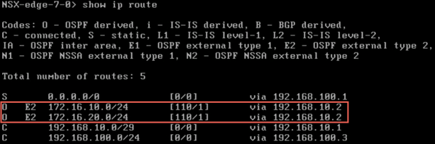
Make sure that the ESG is learning OSPF external routes from the logical router.
To verify connectivity, make sure that an external device in the physical architecture can ping the VMs.
For example:
PS C:\Users\Administrator> ping 172.16.10.10

Pinging 172.16.10.10 with 32 bytes of data:
Reply from 172.16.10.10: bytes=32 time=5ms TTL=61
Reply from 172.16.10.10: bytes=32 time=1ms TTL=61

Ping statistics for 172.16.10.10:
    Packets: Sent = 2, Received = 2, Lost = 0 (0% loss),
Approximate round trip times in milli-seconds:
    Minimum = 1ms, Maximum = 5ms, Average = 3ms
PS C:\Users\Administrator> ping 172.16.20.10

Pinging 172.16.20.10 with 32 bytes of data:
Reply from 172.16.20.10: bytes=32 time=2ms TTL=61
Reply from 172.16.20.10: bytes=32 time=1ms TTL=61

Ping statistics for 172.16.20.10:
    Packets: Sent = 2, Received = 2, Lost = 0 (0% loss),
Approximate round trip times in milli-seconds:
    Minimum = 1ms, Maximum = 2ms, Average = 1ms