


An NSX Data Center for vSphere logical switch reproduces switching functionality (unicast, multicast, broadcast) in a virtual environment completely decoupled from underlying hardware. Logical switches are similar to VLANs, in that they provide network connections to which you can attach virtual machines. The VMs can then communicate with each other over VXLAN if the VMs are connected to the same logical switch. Each logical switch has a segment ID, like a VLAN ID. Unlike VLAN IDs, it's possible to have up to 16 million segment IDs.
When you are adding logical switches, it is important to have in mind a particular topology that you are building. For example, the following simple topology shows two logical switches connected to a single distributed logical router (DLR). In this diagram, each logical switch is connected to a single VM. The two VMs can be on different hosts or the same host, in different host clusters or in the same host cluster. If a DLR does not separate the VMs, the underlying IP addresses configured on the VMs can be in the same subnet. If a DLR does separate them, the IP addresses on the VMs must be in different subnets (as shown in the example).

When you create a logical switch, in addition to selecting a transport zone and replication mode, you configure two options: IP discovery, and MAC learning.
IP discovery minimizes ARP traffic flooding within individual VXLAN segments---in other words, between VMs connected to the same logical switch. IP discovery is enabled by default.
MAC learning builds a VLAN/MAC pair learning table on each vNIC. This table is stored as part of the dvfilter data. During vMotion, dvfilter saves and restores the table at the new location. The switch then issues RARPs for all the VLAN/MAC entries in the table. You might want to enable MAC learning if you are using virtual NICs that are trunking VLANs.
Prerequisites
- vSphere distributed switches must be configured.
- NSX Manager must be installed.
- Controllers must be deployed.
- Host clusters must be prepared for NSX.
- VXLAN must be configured.
- A segment ID pool must be configured.
- A transport zone must be created.
Procedure
- Click Add or the New Logical Switch (
 ) icon.
 - Attach a virtual machine to the logical switch by selecting the switch and clicking the Add Virtual Machine (
 or
or  ) icon.
Results
In .
In Home > Networking:
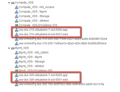
Notice that the virtual wires are created on both of the vSphere distributed switches, Compute_VDS and Mgmt_VDS. This is because both of these vSphere distributed switches are members of the transport zone that is associated with the web and app logical switches.
In Home > Hosts and Clusters > VM > Summary:

On the hosts that are running the VMs that are attached to the logical switch, log in and execute the following commands to view local VXLAN configuration and state information.
-
Displays host-specific VXLAN details.
~ # esxcli network vswitch dvs vmware vxlan list
VDS ID                                           VDS Name      MTU  Segment ID     Gateway IP     Gateway MAC        Network Count  Vmknic Count
-----------------------------------------------  -----------  ----  -------------  -------------  -----------------  -------------  ------------
88 eb 0e 50 96 af 1d f1-36 fe c1 ef a1 51 51 49  Compute_VDS  1600  192.168.250.0  192.168.250.1  ff:ff:ff:ff:ff:ff              0             1
Note: If the esxcli network vswitch dvs vmware vxlan command produces the "Unknown command or namespace" error message, run the /etc/init.d/hostd restart command on the host and then try again.VDS Name displays the vSphere distributed switch to which the host is attached.
The Segment ID is the IP network used by VXLAN.
The Gateway IP is the gateway IP address used by VXLAN.
The Gateway MAC address remains ff:ff:ff:ff:ff:ff.
The Network Count remains 0 unless a DLR is attached to the logical switch.
The Vmknic count should match the number of VMs attached to the logical switch.
-
Test IP VTEP interface connectivity, and verify that the MTU has been increased to support VXLAN encapsulation. Ping the vmknic interface IP address. To find the IP address of vmknic interface in the vSphere Web Client, do these steps:
- Click a host.
- Navigate to .
- Select an appropriate vSphere Distributed Switch.
- In the schematic view of the distributed switch, view the VXLAN and VMkernel port settings.
The -d flag sets the don't-fragment (DF) bit on IPv4 packets. The -s flag sets the packet size.
root@esxcomp-02a ~ # vmkping ++netstack=vxlan -d -s 1570 192.168.250.100
PING 192.168.250.100 (192.168.250.100): 1570 data bytes
1578 bytes from 192.168.250.100: icmp_seq=0 ttl=64 time=1.294 ms
1578 bytes from 192.168.250.100: icmp_seq=1 ttl=64 time=0.686 ms
1578 bytes from 192.168.250.100: icmp_seq=2 ttl=64 time=0.758 ms

--- 192.168.250.100 ping statistics ---
3 packets transmitted, 3 packets received, 0% packet loss
round-trip min/avg/max = 0.686/0.913/1.294 ms
~ #
root@esxcomp-01a ~ # vmkping ++netstack=vxlan -d -s 1570 192.168.250.101 PING 192.168.250.101 (192.168.250.101): 1570 data bytes 1578 bytes from 192.168.250.101: icmp_seq=0 ttl=64 time=0.065 ms 1578 bytes from 192.168.250.101: icmp_seq=1 ttl=64 time=0.118 ms --- 192.168.250.101 ping statistics --- 2 packets transmitted, 2 packets received, 0% packet loss round-trip min/avg/max = 0.065/0.091/0.118 ms
What to do next
Create a logical (distributed) router and attach it to your logical switches to enable connectivity between virtual machines that are connected to different logical switches.
