


The DLR and the ESG rely on the DVS to provide L2 forwarding services for dvPortgroups (both VXLAN and VLAN based) for end-to end connectivity to work.
This means L2 that forwarding services that are connected to DLR or ESG must be configured and operational. In the NSX installation process, these services are provided by “Host Preparation” and “Logical Network Preparation.”
When creating transport zones on multi-cluster DVS configurations, make sure that all clusters in the selected DVS are included under the transport zone. This ensures that the DLR is available on all clusters where DVS dvPortgroups are available.
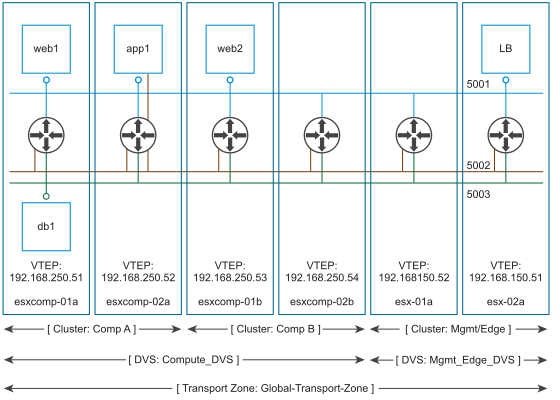
When a transport zone is aligned with DVS boundary, the DLR instance is created correctly.
When a transport zone is not aligned to the DVS boundary, the scope of logical switches (5001, 5002 and 5003) and the DLR instances that these logical switches are connected to becomes disjointed, causing VMs in cluster Comp A to have no access to DLR LIFs.
In the diagram above, DVS “Compute_DVS” covers two clusters, “Comp A” and “Comp B”. The “Global-Transport-Zone” includes both “Comp A” and “Comp B.”
This results in correct alignment between the scope of Logical Switches (5001, 5002, and 5003), and the DLR instance created on all hosts in all clusters where these Logical Switches are present.
Now, let’s look at an alternative situation, where the Transport Zone was not configured to include cluster “Comp A”:
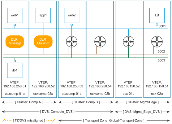
In this case, VMs running on cluster “Comp A” have full access to all logical switches. This is because logical switches are represented by dvPortgoups on hosts, and dvProtgroups are a DVS-wide construct. In our sample environment, “Compute_DVS” covers both “Comp A” an “Comp B."
DLR instances, however, are created in strict alignment with the transport zone scope, which means no DLR instance will be created on hosts in “Comp A."
As the result, VM “web1” will be able to reach VMs “web2” and “LB” because they are on the same logical switch, but VMs “app1” and “db1” will not be able to communicate with anything.
The DLR relies on the Controller Cluster to function, while the ESG does not. Make sure that the Controller Cluster is up and available before creating or changing a DLR configuration.
If the DLR is to be connected to VLAN dvPortgroups, ensure that ESXi hosts with the DLR configured can reach each other on UDP/6999 for DLR VLAN-based ARP proxy to work.
- A given DLR instance cannot be connected to logical switches that exist in different transport zones. This is to ensure all logical switches and DLR instances are aligned.
- The DLR cannot be connected to VLAN-backed portgroups, if that DLR is connected to logical switches spanning more than one DVS. As above, this is to ensure correct alignment of DLR instances with logical switches and dvPortgroups across hosts.
- When selecting placement of the DLR Control VM, avoid placing it on the same host as one or more of its upstream ESGs by using DRS anti-affinity rules if they are in the same cluster. This is to reduce the impact of host failure on DLR forwarding.
- OSPF can be enabled only on a single Uplink (but supports multiple adjacencies). BGP, on other hand, can be enabled on multiple Uplink interfaces, where it is necessary.
