


The following diagram is a high-level illustration for the process NSX follows to create a new DLR.
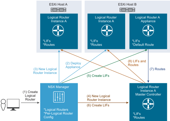
When a UI wizard is submitted with the “Finish” button or an API call is made to deploy a new DLR, the system processes through the following steps:
- NSX Manager receives an API call to deploy a new DLR (directly or from vSphere Web Client, invoked by the UI wizard).
- NSX Manager calls its linked vCenter Server to deploy a DLR Control VM (or a pair, if HA was requested).
- DLR Control VM is powered on and connects back to the NSX Manager, ready to receive configuration.
- If an HA pair was deployed, NSX Manager configures an anti-affinity rule that will keep the HA pair running on different hosts. DRS then takes action to move them apart.
- NSX Manager creates DLR instance on hosts:
- NSX Manager looks up the logical switches that are to be connected to the new DLR to determine which transport zone they belong to.
- It then looks up a list of clusters that are configured in this transport zone and creates the new DLR on each host in these clusters.
- At this point, hosts only know the new DLR ID, but they do not have any corresponding information (LIFs or routes).
- NSX Manager creates a new DLR instance on the Controller Cluster.
- Controller Cluster allocates one of the Controller nodes to be the master for this DLR instance.
- NSX Manager sends the configuration, including LIFs, to the DLR Control VM.
- ESXi hosts (including the one where the DLR Control VM is running) receive slicing information from the Controller Cluster, determine which Controller node is responsible for the new DLR instance, and connect to the Controller node (if there was no existing connection).
- After LIF creation on DLR Control VM, the NSX Manager creates the new DLR’s LIFs on the Controller Cluster.
- DLR Control VM connects to the new DLR instance’s Controller node, and sends the Controller node the routes:
- First the DLR translates its routing table into the forwarding table (by resolving prefixes to LIFs).
- Then The DLR sends the resulting table to the Controller node.
- Controller node pushes LIFs and routes to the other hosts where the new DLR instance exists, via the connection established in step 5.a.
