The following diagram shows two hosts, ESXi Host A and ESXi Host B, where our example “DLR Instance A” is configured and connected to the four VXLAN LIFs.
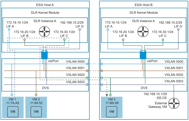
- Each host has an “L2 Switch” (DVS), and a “Router on a stick” (DLR kernel module), connected to that “switch” via a “trunk” interface (vdrPort).
- Note that this “trunk” can carry both VLANs and VXLANs; however, there are no 801.Q or UDP/VXLAN headers present in the packets that traverse the vdrPort. Instead, the DVS uses an internal metadata tagging method to communicate that information to the DLR kernel module.
- When the DVS sees a frame with Destination MAC = vMAC, it knows that it is for the DLR, and forwards that frame to the vdrPort.
- After packets arrive in the DLR kernel module via the vdrPort, their metadata is examined to determine the VXLAN VNI or VLAN ID that they belong to. This information is then used to determine which LIF of which DLR instance that packet belongs to.
- The side effect of this system is that no more than one DLR instance can be connected to a given VLAN or VXLAN.
In cases where more than one DLR instance exists, the diagram above would look like this:
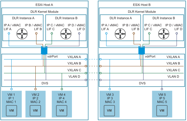
This would correspond to a network topology with two independent routing domains, operating in complete separation from each other, potentially with overlapping IP addresses.