


NSX Edge can be installed using ISO, OVA/OVF, or PXE start. Regardless of the installation method, make sure that the host networking is prepared before you install NSX Edge.
High-Level View of NSX Edge Within a Transport Zone
The high-level view of NSX-T Data Center shows two transport nodes in a transport zone. One transport node is a host. The other is an NSX Edge.
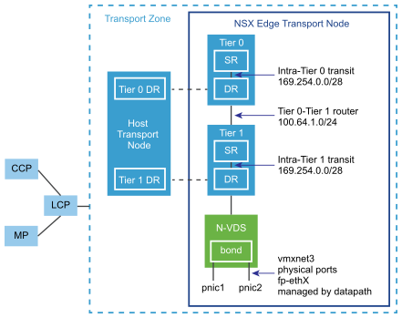
When you first deploy an NSX Edge, you can think of it as an empty container. The NSX Edge does not do anything until you create logical routers. The NSX Edge provides the compute backing for tier-0 and tier-1 logical routers. Each logical router contains a services router (SR) and a distributed router (DR). When we say that a router is distributed, we mean that it is replicated on all transport nodes that belong to the same transport zone. In the figure, the host transport node contains the same DRs contained on the tier-0 and tier-1 routers. A services router is required if the logical router is going to be configured to perform services, such as NAT. All tier-0 logical routers have a services router. A tier-1 router can have a services router if needed based on your design considerations.
By default, the links between the SR and the DR use the 169.254.0.0/28 subnet. These intra-router transit links are created automatically when you deploy a tier-0 or tier-1 logical router. You do not need to configure or modify the link configuration unless the 169.254.0.0/28 subnet is already in use in your deployment. On a tier-1 logical router, the SR is present only if you select an NSX Edge cluster when creating the tier-1 logical router.
The default address space assigned for the tier-0-to-tier-1 connections is 100.64.0.0/10. Each tier-0-to-tier-1 peer connection is provided a /31 subnet within the 100.64.0.0/10 address space. This link is created automatically when you create a tier-1 router and connect it to a tier-0 router. You do not need to configure or modify the interfaces on this link unless the 100.64.0.0/10 subnet is already in use in your deployment.
Each NSX-T Data Center deployment has a management plane cluster (MP) and a control plane cluster (CCP). The MP and the CCP push configurations to each transport zone's local control plane (LCP). When a host or NSX Edge joins the management plane, the management plane agent (MPA) establishes connectivity with the host or NSX Edge, and the host or NSX Edge becomes an NSX-T Data Center fabric node. When the fabric node is then added as a transport node, LCP connectivity is established with the host or NSX Edge.
Lastly, the figure shows an example of two physical NICs (pNIC1 and pNIC2) that are bonded to provide high availability. The datapath manages the physical NICs. They can serve as either VLAN uplinks to an external network or as tunnel endpoint links to internal NSX-T Data Center-managed VM networks.
It is a best practice to allocate at least two physical links to each NSX Edge that is deployed as a VM. Optionally, you can overlap the port groups on the same pNIC using different VLAN IDs. The first network link found is used for management. For example, on an NSX Edge VM, the first link found might be vnic1. On a bare-metal installation, the first link found might be eth0 or em0. The remaining links are used for the uplinks and tunnels. For example, one might be for a tunnel endpoint used by NSX-T Data Center-managed VMs. The other might be used for an NSX Edge-to-external TOR uplink.
You can view the physical link information of the NSX Edge, by logging in to the CLI as an administrator and running the get interfaces and get physical-ports commands. In the API, you can use the GET fabric/nodes/<edge-node-id>/network/interfaces API call. Physical links are discussed in more detail in the next section.
Whether you install NSX Edge as a VM appliance or on bare metal, you have multiple options for the network configuration, depending on your deployment.
Transport Zones and N-VDS
To understand NSX Edge networking, you must know something about transport zones and N-VDS. Transport zones control the reach of Layer 2 networks in NSX-T Data Center. N-VDS is a software switch that gets created on a transport node. The purpose of N-VDS is to bind logical router uplinks and downlinks to physical NICs. For each transport zone that an NSX Edge belongs to, a single N-VDS gets installed on the NSX Edge.
- Overlay for internal NSX-T Data Center tunneling between transport nodes.
- VLAN for uplinks external to NSX-T Data Center.
An NSX Edge can belong to zero VLAN transport zones or many. For zero VLAN transport zones, the NSX Edge can still have uplinks because the NSX Edge uplinks can use the same N-VDS installed for the overlay transport zone. You might do this if you want each NSX Edge to have only one N-VDS. Another design option is for the NSX Edge to belong to multiple VLAN transport zones, one for each uplink.
The most common design choice is three transport zones: One overlay and two VLAN transport zones for redundant uplinks.
To use the same VLAN ID for a transport network for overlay traffic and other for VLAN traffic, such as a VLAN uplink, configure the ID on two different N-VDS, one for VLAN and the other for overlay.
Virtual-Appliance/VM NSX Edge Networking
When you install NSX Edge as a virtual appliance or VM, internal interfaces are created, called fp-ethX, where X is 0, 1, 2, and 3. These interfaces are allocated for uplinks to a top-of-rack (ToR) switches and for NSX-T Data Center overlay tunneling.
When you create the NSX Edge transport node, you can select fp-ethX interfaces to associate with the uplinks and the overlay tunnel. You can decide how to use the fp-ethX interfaces.
On the vSphere distributed switch or vSphere Standard switch, you must allocate at least two vmnics to the NSX Edge: One for NSX Edge management and one for uplinks and tunnels.
In the following sample physical topology, fp-eth0 is used for the overlay tunnel traffic, carrying the TEP IP address. fp-eth1 is used for the tier-0 gateway uplink supporting north-south traffic. fp-eth2 is unused because the topology only consists of gateways. You can use fp-eth2 if an L2 bridge is configured. eth0/vNIC1 is assigned to the management network.
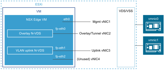
The NSX Edge shown in this example belongs to two transport zones (one overlay and one VLAN) and therefore has two N-VDS, one for tunnel and one for uplink traffic.
This screenshot shows the virtual machine port groups, nsx-tunnel, and vlan-uplink.
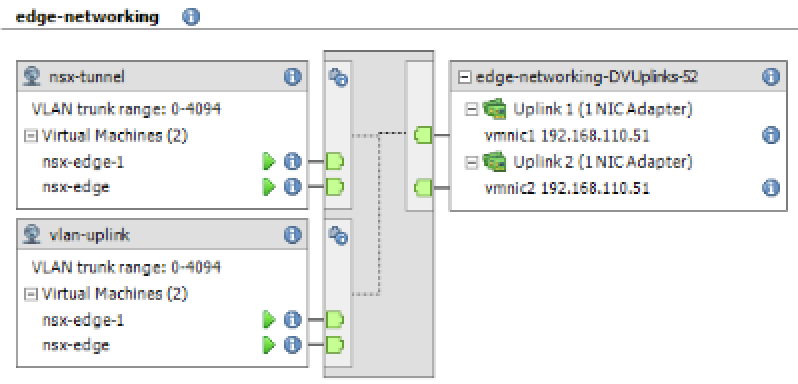
--net:"Network 0-Mgmt" --net:"Network 1-nsx-tunnel" --net:"Network 2=vlan-uplink"
The example shown here uses the VM port group names Mgmt, nsx-tunnel, and vlan-uplink. You can use any names for your VM port groups.
The tunnel and uplink VM port groups configured for the NSX Edge do not need to be associated with VMkernel ports or given IP addresses. This is because they are used at Layer 2 only. If your deployment uses DHCP to provide an address to the management interface, make sure that only one NIC is assigned to the management network.
Notice that the VLAN and tunnel port groups are configured as trunk ports. This is required. For example, on a standard vSwitch, you configure trunk ports as follows: . .
If you are using an appliance-based or VM NSX Edge, you can use standard vSwitches or vSphere distributed switches.
NSX Edge VM can be installed on an NSX-T Data Center prepared host and configured as a transport node. There are two types of deployment:
- NSX Edge VM can be deployed using VSS/VDS port groups where VSS/VDS consume separate pNIC(s) on the host. Host transport node consumes separate pNIC(s) for N-VDS installed on the host. N-VDS of the host transport node co-exists with a VSS or VDS, both consuming separate pNICs. Host TEP (Tunnel End Point) and NSX Edge TEP can be in the same or different subnets.
- NSX Edge VM can be deployed using VLAN-backed logical switches on the N-VDS of the host transport node. Host TEP and NSX Edge TEP must be in different subnets.
Optionally, you can install multiple NSX Edge appliances/VMs on a single host, and the same management, VLAN, and tunnel endpoint port groups can be used by all installed NSX Edges.
With the underlying physical links up and the VM port groups configured, you can install the NSX Edge.
Bare-Metal NSX Edge Networking
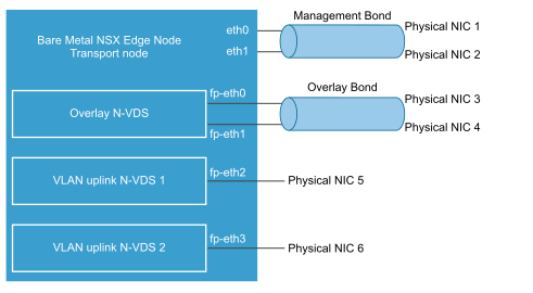
The bare-metal NSX Edge contains internal interfaces called fp-ethX, where X is up to 16 interfaces. The number of fp-ethX interfaces created depends on the number of physical NICs on bare-metal NSX Edge server. Up to four of these interfaces can be allocated for uplinks to top-of-rack (ToR) switches and NSX-T Data Center overlay tunneling.
When you create the NSX Edge transport node, you can select fp-ethX interfaces to associate with the uplinks and the overlay tunnel.
You can decide how to use the fp-ethX interfaces. In the following sample physical topology, fp-eth0 and fp-eth1 are bonded and used for the overlay tunnel traffic, carrying the TEP IP address. fp-eth2 and fp-eth3 are used for the tier-0 gateway uplink supporting north-south traffic. eth0/vNIC1 is assigned to the management network.
NSX Edge Uplink Redundancy
NSX Edge uplink redundancy allows two VLAN equal-cost multipath (ECMP) uplinks to be used on the NSX Edge-to-external TOR network connection.
When you have two ECMP VLAN uplinks, you must also have two TOR switches for high availability and fully meshed connectivity. Each VLAN logical switch has an associated VLAN ID.
When you add an NSX Edge to a VLAN transport zone, a new N-VDS is installed. For example, if you add an NSX Edge node to four VLAN transport zones, as shown in the figure, four N-VDS get installed on the NSX Edge.

- On a vDS switch running version prior (<) to 6.6, enable promiscuous mode for the port connected to NSX Edge VM virtual NIC that provides VLAN connectivity.
- On a vDS switch running version equal to or greater than (>=) 6.6, enable mac learning and disable promiscuous mode. These settings ensure that packets are received at the destination where destination mac address does not match the virtual NIC effective MAC address.
- Enable forged transmit on the vDS switch. Forged transmit enables sending packets with source mac address not matching the virtual NIC effective MAC addresses. These settings are needed to support bridging or L2VPN and DHCP functionality for VLAN networks.
