


The migration coordinator can migrate an NSX Data Center for vSphere environment if it is configured in a supported topology.
Unsupported Features
In all topologies, the following features are not supported:
- OSPF between Edge Services Gateways and northbound routers. You must reconfigure to use BGP.
- IP Multicast.
- IPv6.
For detailed information about which features and configurations are supported, see Detailed Feature Support for Migration Coordinator.
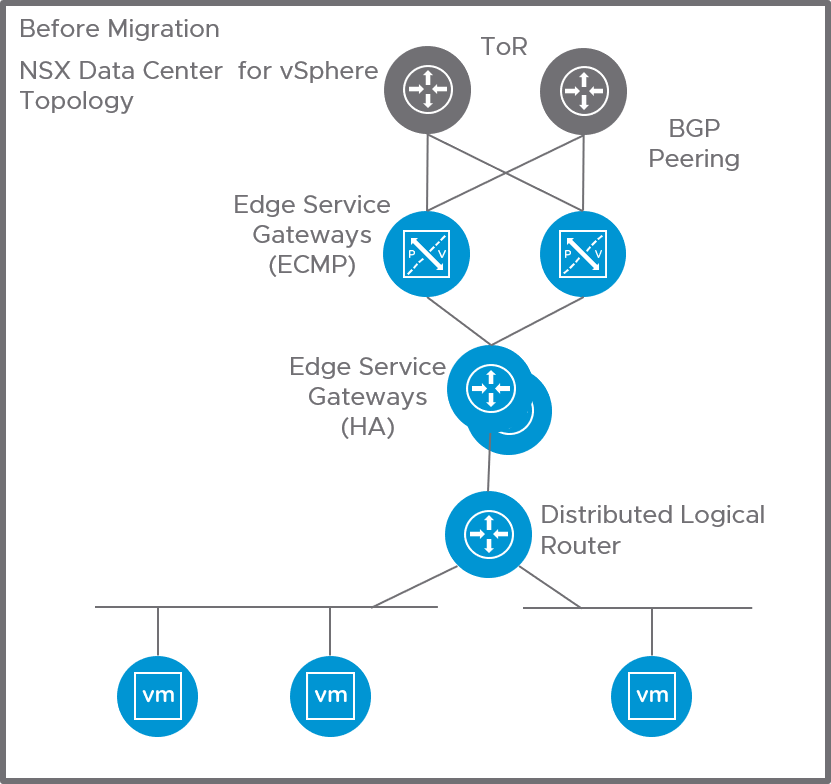
ESG with High Availability and L4-L7 Services (Topology 1)
This topology contains the following configurations:
- A Distributed Logical Router peering with Edge Services Gateway.
- ECMP is not configured.
- The Edge Services Gateways are in a high availability configuration.
- BGP is configured between the Edge Services Gateway and northbound routers.
- Edge Services Gateway can be running L4-L7 services:
- VPN, NAT, DHCP server, DHCP relay, DNS forwarding, Edge Firewall are supported services.
- Load balancer is not supported in this topology.
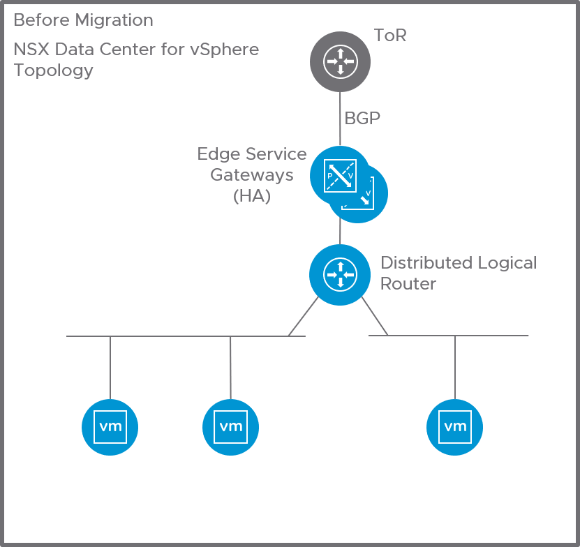
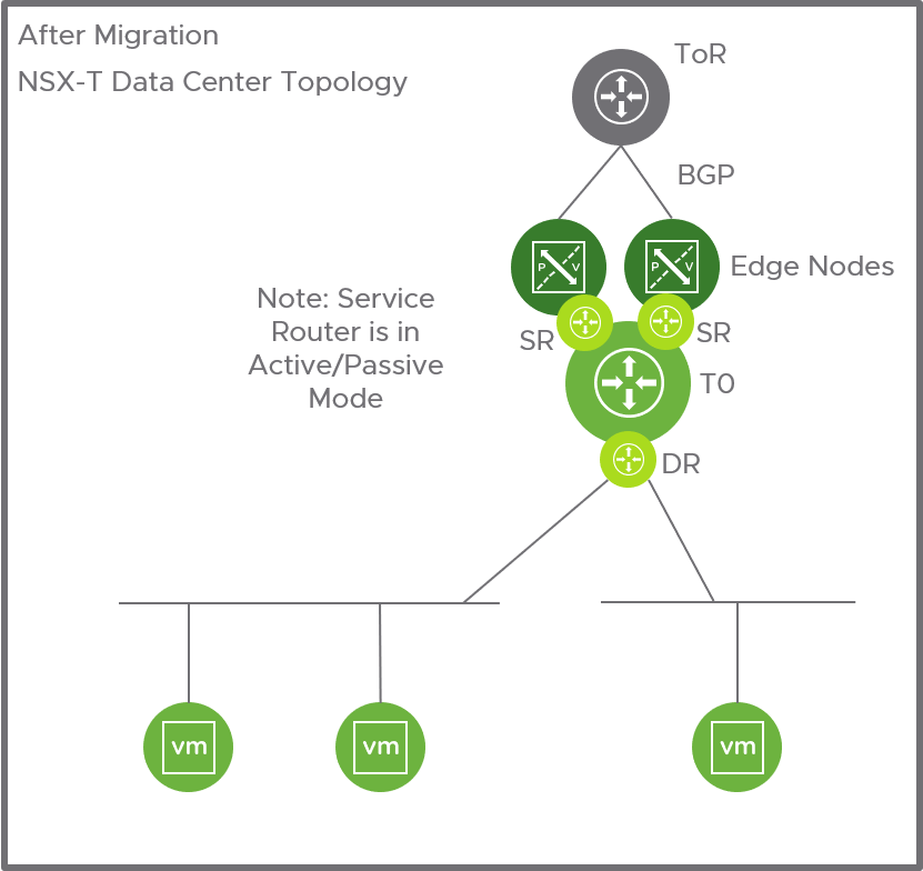
After migration, this configuration is replaced with a tier-0 gateway.
- The tier-0 gateway service router is in active/standby mode.
- The IP addresses of the Distributed Logical Router interfaces are configured as downlinks on the tier-0 gateway.
- The BGP configuration of the ESG is translated to a BGP configuration on the tier-0 gateway.
- Supported services are migrated to the tier-0 gateway.
Note: Depending on your configuration, you might need to provide new IP addresses for the tier-0 gateway uplinks. For example, on an
Edge Services Gateway, you can use the same IP address for the router uplink and for the VPN service. On a tier-0 gateway, you must use the different IP address for VPN and uplinks. See
Example Configuration Issues for more information.
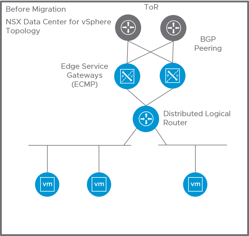
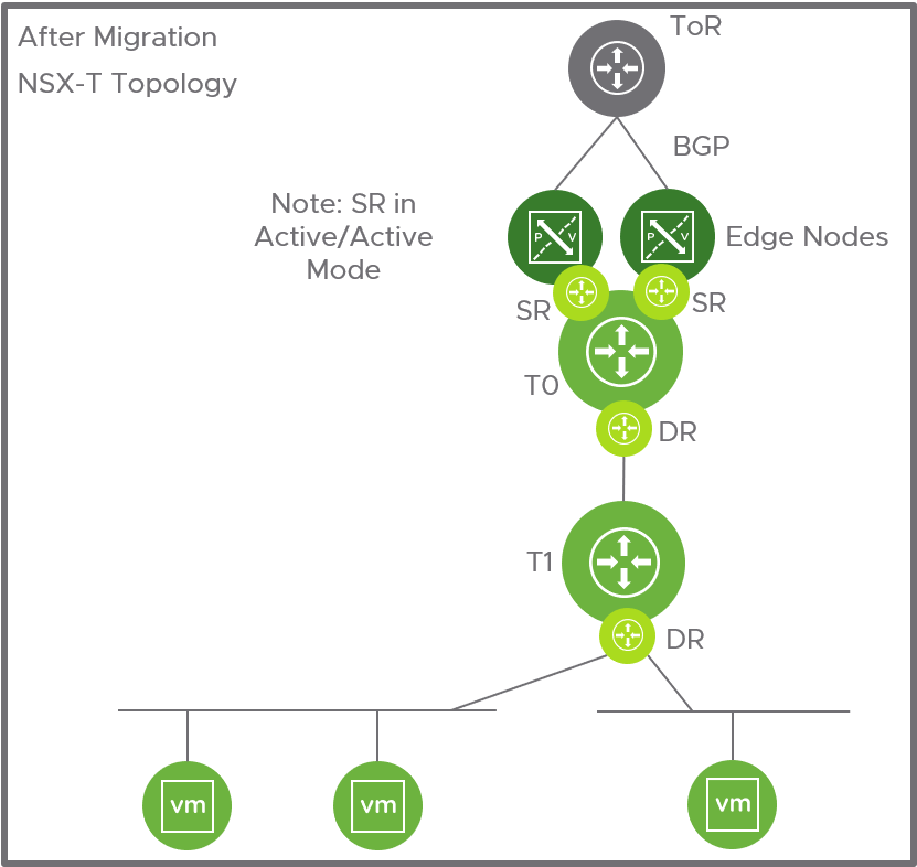
ESG with No L4-L7 Services (Topology 2)
This topology contains the following configurations:
- The Distributed Logical Router has ECMP enabled and peers with multiple Edge Services Gateways.
- BGP is configured between the Edge Services Gateway and northbound routers. The Edge Services Gateways must be configured with the same BGP neighbors. All Edge Services Gateways must point to the same autonomous system (AS).
- If BGP is configured between the Distributed Logical Router and Edge Services Gateway, all BGP neighbors on the Distributed Logical Router must have the same weight.
- Edge Services Gateways must not run L4-L7 services.
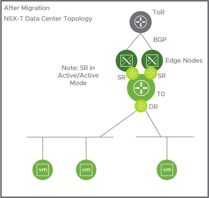
After migration, this configuration is replaced with a tier-0 gateway.
- The tier-0 gateway service router is in active/active mode.
- The IPs of the Distributed Logical Router interfaces are configured as downlinks on the tier-0 Gateway.
- The combined BGP configurations of the Edge Services Gateways are translated to a BGP configuration on the tier-0 gateway. Route redistribution configuration is translated.
- Static routes from Edge Services Gateways and Distributed Logical Routers are translated to static routes on the tier-0 gateway.
Two Levels of ESG with L4-L7 Services on Second-Level ESG (Topology 3)
This topology contains the following configurations:
- Two levels of Edge Services Gateways with Distributed Logical Router.
- The first-level (router-facing) Edge Services Gateways must not run L4-L7 services.
- The first-level Edge Services Gateways must have BGP enabled and have at least one BGP neighbor.
- The second-level Edge Services Gateways have ECMP enabled and peer with the first-level Edge Services Gateways.
- The second-level Edge Services Gateways can run L4-L7 services:
- NAT, DHCP server, DHCP relay, DNS forwarding, inline load balancer, and Edge firewall are supported.
- VPN is not supported.
After migration, this configuration is replaced with a tier-0 gateway and a tier-1 gateway.
- The first-level Edge Services Gateways are replaced with a tier-0 gateway. The service router is in active/active mode.
- The IPs of the first-level Edge Services Gateway uplinks are used for the tier-0 gateway uplinks.
- The tier-0 gateway peers with northbound routers using BGP.
- The second-level Edge Services Gateways are translated to a tier-1 gateway, which is linked to the tier-0 gateway.
- The IPs of the Distributed Logical Router interfaces are configured as downlinks on the tier-1 Gateway.
- Any services running on the second-level Edge Services Gateway are migrated to the tier-1 gateway.
- The BGP configuration on the first-level Edge Services Gateways is translated to a BGP configuration for the tier-0 gateway. Route redistribution configuration is translated.
- Static routes from Edge Services Gateways and Distributed Logical Routers are translated to static routes on the tier-0 gateway. Static routes between the Distributed Logical Router and second-level Edge Services Gateways are not needed, and so are not translated.
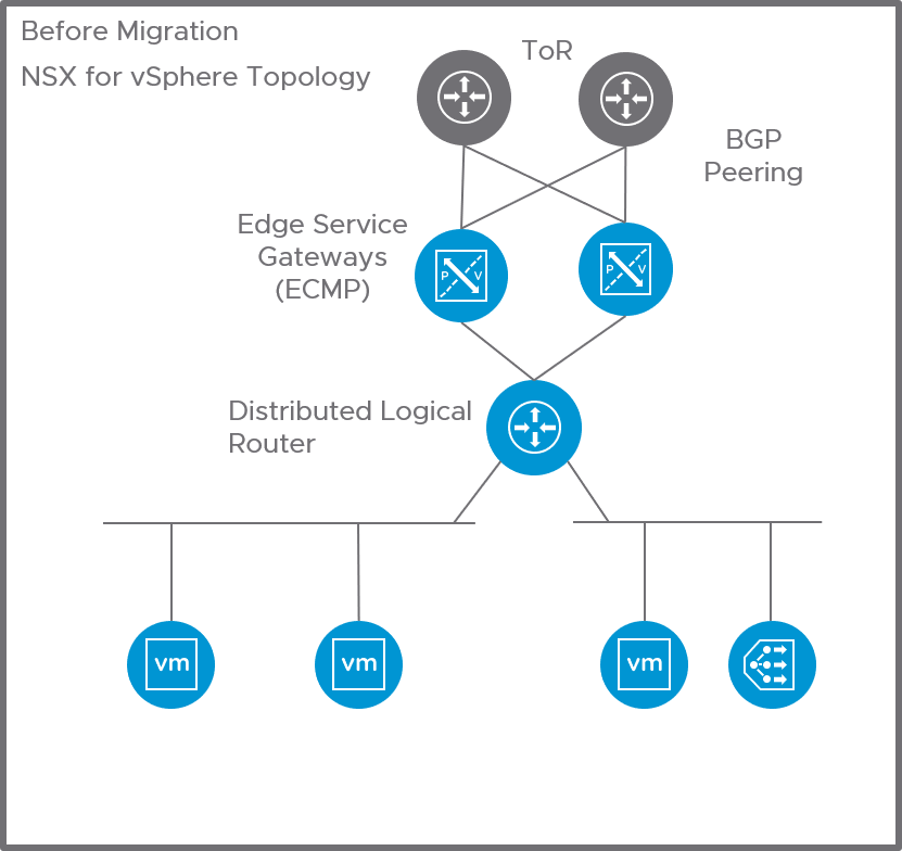
One-Armed Load Balancer (Topology 4)
This topology contains the following configurations:
- The Distributed Logical Router has ECMP enabled and peers with multiple Edge Services Gateway.
- BGP is configured between the Edge Services Gateway and northbound routers. All Edge Services Gateways must be configured with the same BGP neighbors. All Edge Services Gateways must point to the same autonomous system (AS).
- If BGP is configured between the Distributed Logical Router and Edge Services Gateway, all BGP neighbors on the Distributed Logical Router must have the same weight.
- The router-facing Edge Services Gateways must not run L4-L7 services.
- An Edge Services Gateway is attached to the Distributed Logical Router to perform load balancing services. It can also run Edge firewall and DHCP.
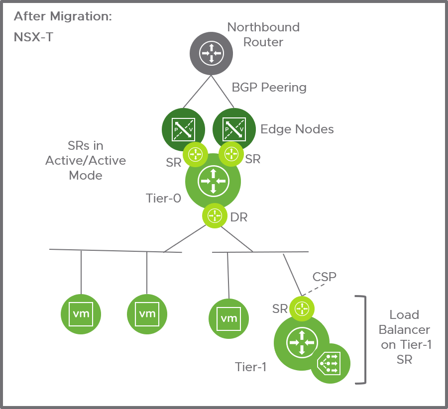
After migration, the top-level Edge Services Gateways and the Distributed Logical Router are replaced with a tier-0 gateway. The
Edge Services Gateway performing load balancing services is replaced with a tier-1 gateway.
- The tier-0 gateway service router is in active/active mode.
- The IPs of the Distributed Logical Router interfaces are configured as downlinks on the tier-0 Gateway.
- The combined BGP configurations of the top-level Edge Services Gateways are translated to a BGP configuration on the tier-0 gateway. Route redistribution configuration is translated.
- Static routes from the top-level Edge Services Gateways and Distributed Logical Routers are translated to static routes on the tier-0 gateway.
- The load balancing configuration on the Edge Services Gateway is translated to a one-arm load balancer configuration on the tier-1 Service Router.
VLAN-Backed Micro-Segmentation (Topology 5)
This topology uses Distributed Firewall to provide firewall protection to workloads connected to VLAN-backed distributed port groups.
This topology uses the following
NSX Data Center for vSphere features:
- NSX Manager
- Host Preparation Distributed Firewall only)
- Distributed Firewall
- Service Composer
- Grouping Objects
This topology must not contain the following features:
- Transport Zone
- VXLAN
- Logical Switch
- Edge Services Gateway
- Distributed Logical Router
