


An example of an NSX-T Data Center cluster prepared using VDS as the host switch.
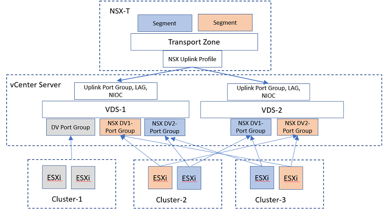
In the sample topology diagram, two VDS switches are configured to manage NSX-T Data Center traffic and vSphere traffic.
VDS-1 and VDS-2 are configured to manage networking for ESXi hosts from Cluster-1, Cluster-2, and Cluster-3. Cluster-1 is prepared to run only vSphere traffic, whereas, Cluster-2 and Cluster-3 are prepared as host transport nodes with these VDS switches.
In vCenter Server, uplink port groups on VDS switches are assigned physical NICs. In the topology, uplinks on VDS-1 and VDS-2 are assigned to physical NICs. Depending on the hardware configuration of the ESXi host, you might want to plan out how many physical NICs to be assigned to the switch. In addition to assiging uplinks to the VDS switch, MTU, NIOC, LLDP, LAG profiles are configured on the VDS switches.
After VDS switches are configured in NSX-T Data Center, add an uplink profile.
When preparing a cluster by applying a transport node profile (on a VDS switch), the uplinks from the transport node profile is mapped to VDS uplinks.
After preparing the clusters, ESXi hosts on cluster-2 and Cluster-3 manage NSX-T Data Centertraffic, while cluster-1 manage vSphere traffic.
