Follow this workflow to configure EVPN with Route Server mode.

Prerequisites

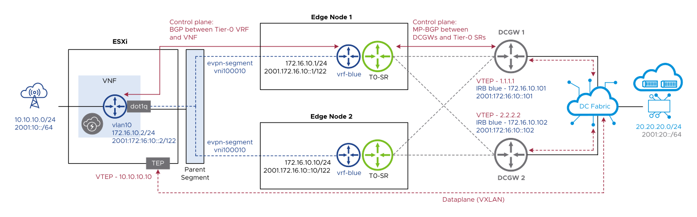
A typical BGP EVPN Route Server mode deployment topology has the following characteristics:

  • The tier-0 gateway must be in active-active mode.
  • There are least two data center gateways connected to the edge nodes.
  • There are point-to-point uplinks between edge nodes and data center gateways over VLAN segments.
  • There are eBGP peering sessions between edge nodes and data center gateways using loopback interfaces.
  • The ESXi node TEP network must have connectivity to the data center gateway VTEP IP addresses.
  • There are southbound VMs and workloads connected to the VNF southbound interfaces using regular NSX segments.
  • There are eBGP peering sessions between the VNF and service ports of tier-0 VRF gateways.

The following diagram depicts a typical BGP EVPN Route Server mode deployment topology:

""

Procedure

  1. Configure a VNI pool. See Add an EVPN/VXLAN VNI Pool.
  2. Configure an EVPN tenant. See Configure an EVPN Tenant.
  3. Configure EVPN BFD between the ESXi nodes and data center gateways. See Configure EVPN BFD.
  4. Configure a tier-0 gateway and enable EVPN. See Configure a Tier-0 Gateway for EVPN Route Server Mode.
  5. Configure BGP neighbors. See Configure BGP Neighbors for a Tier-0 Gateway.
  6. Configure a tier-0 VRF gateway. See Configure a Tier-0 VRF Gateway for EVPN Route Server Mode.
  7. Configure networking for onboarding the tenant VNF. See Onboard a Tenant VNF for EVPN Route Server Mode.
  8. In NSX-T Data Center, verify the following:
    Verification Steps
    Verify the tier-0 SR BGP neighbor session status.
    1. Select Networking > Tier-0 Gateways.
    2. Click the menu icon (three dots) for the tier-0 VRF gateway and select Generate BGP Summary.
    3. Verify that Connection Status displays Established.
    4. Verify that Address Families displays L2VPN EVPN.
    Verify the tier-0 VRF BGP neighbor session status.
    1. Select Networking > Tier-0 Gateways.
    2. Click the menu icon (three dots) for the tier-0 VRF gateway and select Generate BGP Summary.
    3. Verify that the neighbor Connection Status displays Established.
    Verify the tier-0 VRF gateway routing table.
    1. Select Networking > Tier-0 Gateways.
    2. Click the menu icon (three dots) for the tier-0 VRF gateway and select Download Routing Table.
    3. Select the transport node (edge node) and for Source, select BGP.
    4. Click Download.
    5. Verify that the remote nodes received from the external router are installed in the tier-0 VRF gateway routing table.
  9. In the ESXi NSX CLI, verify the following.
    • Verify the status of the VTEP group for the VNI.

      get logical-switch <vni> vtep-group

    • Verify the MAC address for the L2 VNI.

      get logical-switch <vni> mac-table

    • Verify the ARP table for the L2 VNI.

      get logical-switch <vni> arp-table