As an admin, you can configure a physical server for NSX-T networking through the NSX Manager GUI.

Alternatively, you can run the Ansible script to achieve the same goal. See Secure Workloads on Windows Server 2016/2019 Bare Metal Servers for configuring Windows physical servers using Ansible. However, it is recommended to use the NSX Manager UI to prepare physical servers for NSX-T networking.

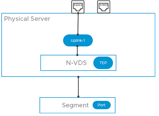
Physical servers supports an overlay and VLAN transport zone. You can use the management interface to manage the physical server server. The application interface allows you to access the applications on the physical server. These NIC configurations are supported on a physical server:

  • Single physical NIC cards provide an IP address for both the management and the application IP interfaces.
  • Dual physical NIC cards provide a physical NIC and a unique IP address for the management interface. Dual physical NIC cards also provide a physical NIC, and a unique IP address for the application interface.
  • Windows servers: Dual physical NIC cards in a bonded configuration provide a unique IP address for both the management interface and the application interface. Such physical NIC bonds are supported through bonds created in the OS. Bond must be configured in the Switch Independent mode. Traffic running on management network is not supported on a bonded teaming interface.
  • Linux servers: Bond interface only supports underlay mode (VLAN 0). Supported flavors are CentOS 7.9, CentOS 8.3, RHEL 7.9 and RHEL 8.3. Physical NIC bonds are supported in Active/Active and Active/Standby mode through OVS switch.
Unlike preparation of a standalone or a managed ESXi host that ends when it becomes a transport node, for a physical sever, complete server preparation extends to attaching the application interface of the physical server to an NSX-T segment.
After preparing the host as a transport node, you must complete the following tasks to finish configuring a physical server.
  1. Create a segment port on an NSX-T segment.
  2. Attach application interface of the physical server to the segment port.

Create a NSX-T segment port and attach it to an application interface of the physical server.

Prerequisites

  • A transport zone must be configured.
  • An uplink profile must be configured, or you can use the default uplink profile.
  • An IP pool must be configured, or DHCP must be available in the network deployment.
  • At least one physical NIC must be available on the host node.
  • Hostname
  • Management IP address
  • User name
  • Password
  • A segment (VLAN or Overlay), depending upon your requirement, must be available to attach to the application interface of the physical server.
  • Verify that the required third-party packages are installed. Third party packages must be installed on the physical server so that its physical NICs are available during transport node configuration. See Install Third-Party Packages on a Physical Server.
  • On Windows physical servers, log in as an administrator to install NSX.
  • Starting with NSX Data Center 3.2.1, on Linux physical servers, you can update the sudoers file to add custom users with minimal privileges. The custom users allows you to install NSX without root permissions.

    After configuring visudo, run the following command to access the /etc/sudoers file.

    $ sudo visudo

    RHEL/CentOS/OEL/SLES:

    tester ALL=(ALL) /usr/bin/rpm, /usr/bin/nsxcli, /usr/bin/systemctl restart openvswitch
    Ubuntu:
    tester ALL=(ALL) /bin/ls, /usr/bin/sudo, /usr/bin/dpkg, /bin/nsxcli

Procedure

  1. From a browser, log in with admin privileges to an NSX Manager at https://<nsx-manager-ip-address>.
  2. Go to System → Fabric → Nodes → Host Transport Node.
  3. On the Host Transport Node page, click + Add Host Node.
  4. On the Host Details window, enter the following details.
    Option Description
    Name and Description Enter the name to identify the physical server.

    You can optionally add the description of the operating system used for the host or physical server server.

    IP Addresses Enter the host or physical server server IP address.
    Operating System Select an operating system that mentions physical server. For example, if the operating system on the physical server is CentOS, select CentOS Physical Server. NSX-T identifies bare metal servers as physical servers.

    Depending on your physical server, you can select any of the supported operating systems. See System Requirements.

    Important: Among the different flavors of Linux supported, you must know the distinction between a physical server server running a Linux distribution versus using a Linux distribution as a hypervisor host. For example, selecting Ubuntu Server as the operating system means setting up a physical server server running a Linux server, whereas selcting Ubuntu KVM means the Linux hypervisior deployed is Ubuntu.
    Username and Password Enter the host user name and password.
    SHA-256 Thumbprint

    This is an optional step.

    Enter the host thumbprint value for authentication.

    If you leave the thumbprint value empty, you are prompted to accept the server provided value. It takes a few seconds for NSX-T Data Center to discover and authenticate the host.

  5. Click Next.
  6. On the Prepare Host window, enter the following details. You can only configure a single N-VDS switch for a single physical server.
    Option Description
    Name Enter a name for the N-VDS host switch.
    Transport Zone From the drop-down menu, select a transport zone that this transport node.
    Uplink Profile Select an existing uplink profile from the drop-down menu or create a custom uplink profile. You can also use the default uplink profile.
    LLDP Profile By default, NSX-T only receives LLDP packets from a LLDP neighbor.

    However, NSX-T can be set to send LLDP packets to and receive LLDP packets from a LLDP neighbor.

    Uplinks-Physical NICs Mapping

    To map an uplink in NSX-T with a physical NIC or a bonded interface, enter the name of the physical NIC or bonded interface as configured on the physical server. For example, if teaming1 is the name of the interface you configured on the Windows server, then enter teaming1 in the Physical NICs field.

    Important:
    • You cannot map one uplink to a physical NIC and another uplink to a bonded interface.
    • If you are using a bonded interface, both NICs must be configured to function at the same packet transfer speed.
    On Windows servers, you can configure teaming interfaces (bonded interfaces). The supported load balancing algorithms for teaming interfaces on Windows servers are:
    • TransportNodes load balancing algorithm

    • MacAddresses load balancing algorithm

    • IPAddresses load balancing algorithm

      In the teaming interface configuration, set Teaming Mode to Switch Independent mode. For more details, see Windows documentation.

    On Linux servers, you can configure a bonded interface by updating the network-scripts files. For more information, see Linux documentation.

  7. Click Next.
  8. As the host is configured, the physical server progress is displayed.
  9. On the Configure NSX window, verify status of host preparation. Based on whether you want to proceed with further configuration, these choices are available:
    Description
    Click Select Segment If the physical server preparation was successful, click Select Segment. In the next part of the procedure, you select a segment to attach the physical server's application interface through the NSX agent. Proceed to the next step.
    Click Continue Later

    If you click Continue Later button, then preparation ends without the application interface configured. You can later attach the segment port to the application interface. Go to Networking → Segments. Configure application interface for the BMS.

    Preparation Failed

    If preparation failed, go to the Host Transport Node page (System → Fabric → Nodes → Host Transport Node). Identify the physical server, check if the Configuration State is in Failed state. Click Resolve to retry host preparation.

  10. If you proceed to select a segment for the physical server, perform the following steps:
    1. From the list of segments connected to the transport zone you configured for the physical server, select the one to configure for the server.
    2. Click the vertical ellipses and click Edit to customize segment properties.
      Note: Only properties related to a segment can be edited. Admin can modify: Segment Name, Connected Gateway, Subnet, Uplink Teaming Policy, IP Address Pool.
  11. To add a new segment port on an NSX-T segment, got to the Select Segment window, click Add Segment Port. The segment port page is auto-populated.
    Option Description
    Name Enter the Segment Port name.
    ID The virtual interface UUID is auto-populated.
    Type Static is auto-populated as the node is of the type, physical server.
    Context ID Transport node UUID is auto-populated.
    Note: Alternatively, you can also run the API command, https://<NSX-Manager-IP-address>/PATCH /policy/api/v1/infra/segments/<segment-id>/ports/<port-id>.

    Where, <port-id> is the virtual interface UUID, which is displayed on NSX Manager.

  12. To attach application interface of physical server to a segment port, go to the Set Segment Port window, expand the Attach Application Interface section and enter these details:
    Note: The Attach Application Interface section is only applicable for physical servers.
    Option Description
    Name You can change the system-generated application interface name.

    On a Linux physical server, run ovs-vsctl show to verify the application interface name.

    Context ID To enable the application interface configuration, enter the host node ID.
    Assign Existing IP Use an existing IP so that it can be used for migration of the application interface.
    Assign New IP Used when configuring an overlay network. Select an IP assignment method on the segment - IP pool, DHCP, or Static. When you assign a new IP address for the application interface, complete the configuration by providing the IP address, Routing Table and Default Gateway details.
  13. Click Save.
  14. View the summary of the network configuration represented by topology diagram.
  15. On the Host Transport Node page, select the physical server, and click Switch Visualization for the server. It must represent the network you configured on the physical server.

Results

The physical server is configured for NSX-T networking.