After the reference host is associated with the custom image profile and configured with a VSS or DVS switch, deploy the reference host as a NSX-T transport node with NSX-T enabled DVS switch.
Procedure
- From a browser, log in to NSX-T at https://<NSXManager_IPaddress>.
- To locate the reference host, navigate the UI based on the NSX-T Data Center version:
- (NSX-T Data Center 3.2.2 or later) System > Fabric > Hosts and select the Cluster tab.
-
(NSX-T Data Center 3.2.1 or earlier) System > Fabric > Nodes > Host Transport Nodes
- Create a VLAN transport zone to define the span of the virtual network. The span is defined by attaching N-VDS switches to the transport zone. Based on this attachment, N-VDS can access segments defined within the transport zone. See Create a Transport Zone.
- Create a VLAN segment on the transport zone. The created segment is displayed as a logical switch.
- Navigate to Networking -> Segments.
- Select the transport zone to attach the segment.
- Enter VLAN ID.
- Click Save.

- Create an uplink profile for the reference host that defines how an N-VDS or VDS switch connects to the physical network. See, Create an Uplink Profile.

- Configure the reference host as a transport node. See Configure a Managed Host Transport Node.
- In the Host Transport Node page, select the reference host.
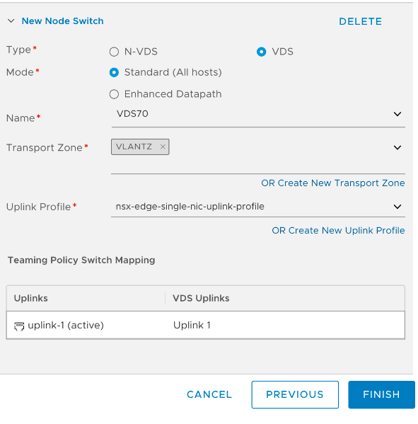
- (On a N-VDS switch) Click Configure NSX and select the previously created transport zone, N-VDS, uplink profile.
- (On a VDS switch) Click Configure NSX and select the previously created transport zone, VDS, uplink profile.

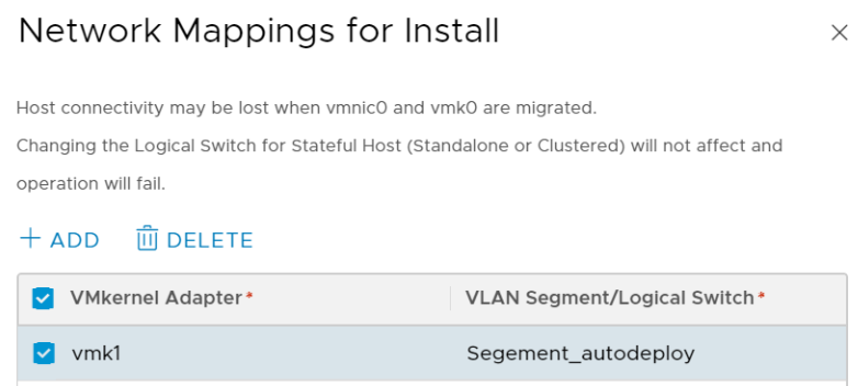
- In the Network Mappings to Install section, click Add Mapping to add the VMkernel to Segment/Logical switch mapping.
Note: On a VDS switch, VMkernel adapter migration is not supported.

- Click Finish to begin installation of NSX-T on the reference host.
(On a VDS switch) After installation, configuration status of the reference host is displayed as Success. In the vCenter Server, the VDS switch is displayed as NSX switch.
(On an N-VDS switch) During installation, VMkernel adapters and physical NICs are migrated from a VSS or DVS switch to an N-VDS switch. After installation, configuration status of the reference host is displayed as Success.
Note: The reference host is listed under Other Hosts.
- In vCenter Server, verify that the PNICs and VMkernels adapters on the VSS switch are migrated and connected to the N-VDS switch.
Note: On a VDS switch, VMkernel adapter and physical NIC migration is not supported. Attaching a VMkernel adapter to an NSX Distributed Virtual port group is not supported.

What to do next
Extract and Verify the Host Profile. See Extract and Verify the Host Profile.