Add the networking components to create the logical network topology in the NSX-T. You can create the same logical topology as your existing NSX-V or create a new topology, if necessary.
You must also pre-configure the networking services that are required for your applications to run before the VMs are moved to the new NSX-T.
The following procedure outlines the workflow for creating the NSX-T logical topology. For a detailed information about creating and configuring the networking objects, see the NSX-T Data Center Administration Guide. If you plan to create the topology using APIs, see the NSX-T Data Center API Guide for more information.
Procedure
Add tier-0 and tier-1 gateways depending on the requirements of your NSX-T network topology.
Add NSX-T overlay segments with the same subnet address as the Logical Switches in NSX-V. Similarly, add NSX-T VLAN segments with the same subnet address as the Distributed Virtual Port Group (DVPG) VLANs in NSX-V.
The same subnet address helps in ensuring that the IP addresses of the workload VMs are retained after the VMs move to
NSX-T segments.
You must create the segments with the SOURCE replication mode, and change the mode to MTEP only after the migration is done.
To migrate Distributed Firewall configuration from your NSX-V environment, ensure that the following requirements are met:
The overlay segments in NSX-T must have the same virtual network identifier (VNI) as the Logical Switches in NSX-V. You must use the NSX-T APIs to create the overlay segments. You cannot create overlay segments with the same VNI in the NSX Manager UI.
The VLAN segments in NSX-T must have the same VLAN IDs as the VLAN Distributed Virtual Port Groups in NSX-V.
Note: VLAN Distributed Virtual Port Group must be associated only with a VLAN ID. VLAN Trunk is not supported.
If Layer 3 services such as Network Address Translation, Load Balancing, VPN, and so on, are configured on your NSX-V Edge Services Gateway, configure equivalent services on the tier-1 or tier-0 gateway of your NSX-T environment. Make sure that both steps 4 and 5 are done.
If Layer 3 services are not configured, skip steps 4 and 5 and proceed directly to step 6.
Caution: Be careful not to enable route advertisement and Layer 3 services on the tier-1 gateway while the north-south traffic is being routed through the Edge Services Gateway. It can conflict with the
NSX-V environment. Also, remember that your workload VMs are not yet moved to
NSX-T. The best time to enable route advertisement and Layer 3 network services is when you are ready to switch the default gateway for north-south traffic to the
NSX-T side.
In NSX Manager, navigate to Networking > Tier-1 Gateways.
Click the vertical ellipses next to the tier-1 gateway, and then click Edit.
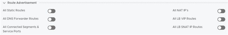
Expand the Route Advertisement section, and turn off all the toggle buttons for the L3 services.
For example:
Connect the uplink interface of the tier-0 gateway to a transit VLAN segment.
Optionally, configure dynamic route peering between tier-0 gateway and the north-facing physical routers. If you configure dynamic routing, ensure that
Route Redistribution Status is turned off on the tier-0 gateway so that no subnets are advertised in the
NSX-T environment. You must enable
Route Redistribution Status when you are ready to switch the default gateway to the
NSX-T side for routing the north-south traffic.
In NSX Manager, navigate to Networking > Tier-0 Gateways.
Click the vertical ellipses next to the tier-0 gateway, and then click Edit.
Expand the Route Re-Distribution section, and turn-off the Route Re-distribution Status toggle button.
Attach the overlay segments to the downlinks of the tier-0 or tier-1 gateway.
Turn off
Connectivity on the segment while the north-south traffic is being routed through the Edge Services Gateway in your
NSX-V environment. Turn on the segment connectivity only when you are ready to switch the default gateway to the
NSX-T side for routing the north-south traffic.
In NSX Manager, navigate to Networking > Segments.
Click the vertical ellipses next to the segment, and then click Edit.
Turn off the Connectivity option to disconnect the segment from the network topology.