


NSX supports multisite deployments where you can manage all the sites from one NSX Manager cluster.
- Disaster recovery
- Active-active
The following diagram illustrates a disaster recovery deployment.
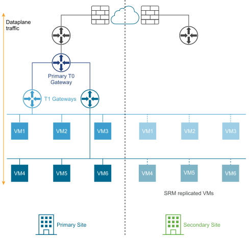
In a disaster recovery deployment, NSX at the primary site handles networking for the enterprise. The secondary site stands by to take over if a catastrophic failure occurs at the primary site.
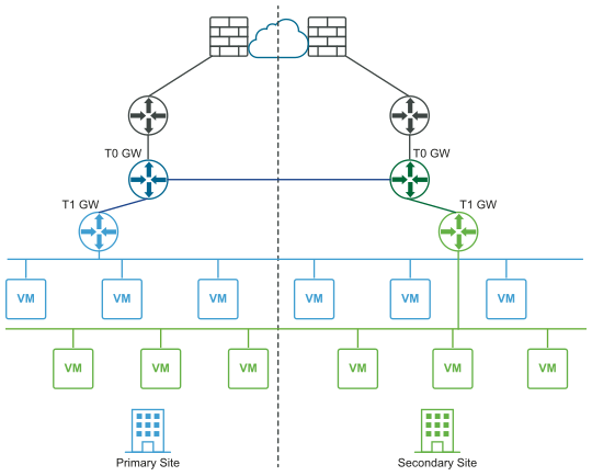
The following diagram illustrates an active-active deployment.
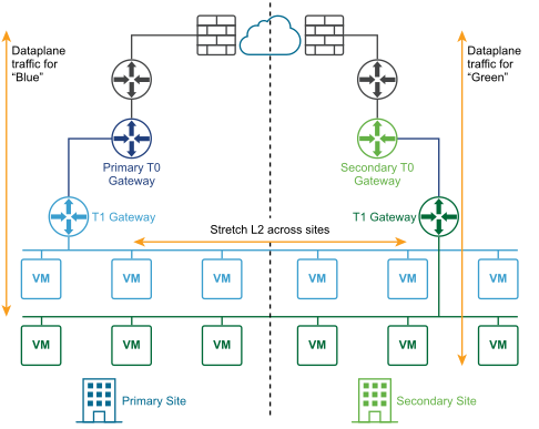
You can deploy two sites for automatic or manual/scripted recovery of the management plane and the data plane.
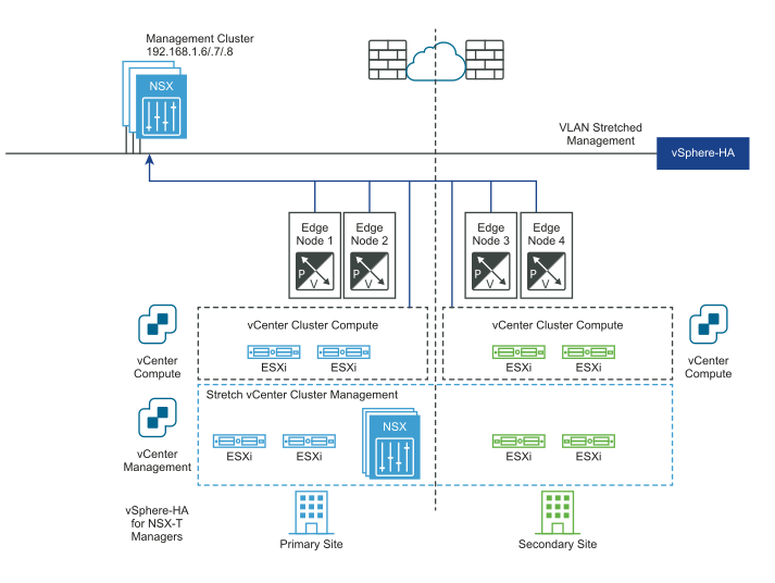
Automatic Recovery of the Management Plane
- A stretched vCenter cluster with high availability (HA) across sites configured.
- A stretched management VLAN.
The NSX Manager cluster gets deployed on the management VLAN and is physically in the primary site. If there is a primary site failure, vSphere HA restarts the NSX Managers in the secondary site. All the transport nodes reconnect to the restarted NSX Managers automatically. This process takes about 10 minutes. During this time, the management plane is not available but there is no impact to the data plane.
The following diagrams illustrates automatic recovery of the management plane.
Before the disaster:
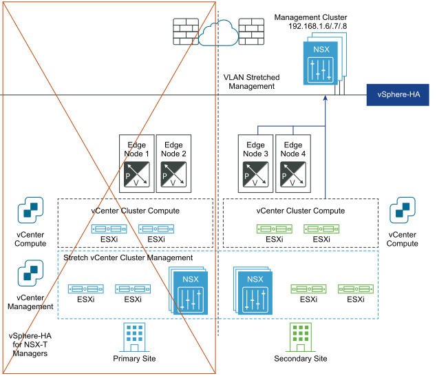
After disaster recovery:
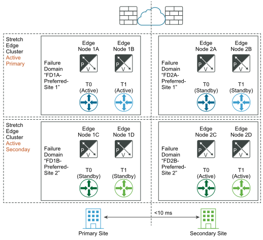
Automatic Recovery of the Data Plane
To achieve automatic recovery of the data plane, you can configure failure domains for Edge nodes. You can group Edge nodes within an Edge cluster in different failure domains. NSX Manager automatically places any new active tier-1 gateway in the preferred failure domain, and the standby tier-1 gateway in the other domain. Tier-1 gateways deployed prior to the failure domain creations keep their original Edge node placement and might not be running where you want. If you want to fix their placement, edit the T1 and manually select the Edge Nodes for T1-Active and T1-Standby gateways.
- The maximum latency between Edge nodes is 10 ms.
- If asymmetric north-south routing is not achievable, for example a physical firewall is used northbound to the NSX Edge node, then the HA mode for the tier-0 gateway must be active-standby, and the failover mode must be preemptive.
- If asymmetric north-south routing is possible, for example the two locations are two buildings without any physical firewall between them, then the HA mode for the tier-0 gateway can be active-active.
The Edge nodes can be VMs or bare metal. The failover mode of the tier-1 gateway can be preemptive or non-preemptive, but preemptive is recommended to guarantee that the tier-0 and tier-1 gateways are in the same location.
- Using the API, create failure domains for the two sites, for example, FD1A-Preferred_Site1 and FD2A-Preferred_Site1. Set the parameter preferred_active_edge_services to
truefor the primary site and set it tofalsefor the secondary site.POST /api/v1/failure-domains { "display_name": "FD1A-Preferred_Site1", "preferred_active_edge_services": "true" } POST /api/v1/failure-domains { "display_name": "FD2A-Preferred_Site1", "preferred_active_edge_services": "false" } - Using the API, configure an Edge cluster that you have stretched across the two sites. For example, the cluster has Edge nodes EdgeNode1A and EdgeNode1B in the primary site, and Edge nodes EdgeNode2A and EdgeNode2B in the secondary site. The active tier-0 and the active tier-1 gateways run on EdgeNode1A and EdgeNode1B. The standby tier-0 and the standby tier-1 gateways run on EdgeNode2A and EdgeNode2B.
- Using the API, associate each Edge node with the failure domain for the site. To get the data about the Edge node, run the
GET /api/v1/transport-nodes/<transport-node-id>API . Use the GET API result as the input for thePUT /api/v1/transport-nodes/<transport-node-id>API, with the property, failure_domain_id, set appropriately. For example,GET /api/v1/transport-nodes/<transport-node-id> Response: "resource_type": "TransportNode", "description": "Updated NSX configured Test Transport Node", "id": "77816de2-39c3-436c-b891-54d31f580961", ... } PUT /api/v1/transport-nodes/<transport-node-id> { "resource_type": "TransportNode", "description": "Updated NSX configured Test Transport Node", "id": "77816de2-39c3-436c-b891-54d31f580961", ... "failure_domain_id": "<UUID>", } - Using the API, configure the Edge cluster to allocate nodes based on the failure domain. To get the data about the Edge cluster, run the
GET /api/v1/edge-clusters/<edge-cluster-id>API. Use the GET API result as the input for thePUT /api/v1/edge-clusters/<edge-cluster-id>API, with the additional property, allocation_rules, set appropriately. For example,GET /api/v1/edge-clusters/<edge-cluster-id> Response: { "_revision": 0, "id": "bf8d4daf-93f6-4c23-af38-63f6d372e14e", "resource_type": "EdgeCluster", ... } PUT /api/v1/edge-clusters/<edge-cluster-id> { "_revision": 0, "id": "bf8d4daf-93f6-4c23-af38-63f6d372e14e", "resource_type": "EdgeCluster", ... "allocation_rules": [ { "action": { "enabled": true, "action_type": "AllocationBasedOnFailureDomain" } } ], } - Create the tier-0 and the tier-1 gateways using the API or the NSX Manager UI.
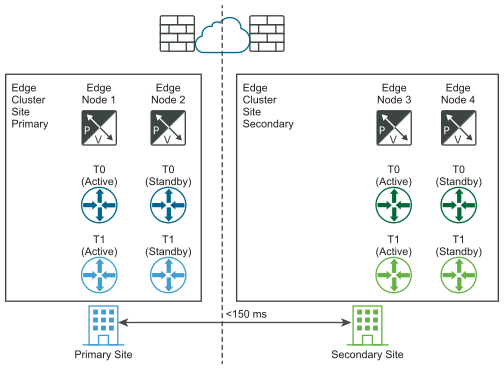
If a full primary site failure occurs, the tier-0 standby and the tier-1 standby in the secondary site automatically take over and become the new active gateways.
The following diagrams illustrate automatic recovery of the data plane.
Before the disaster:
After disaster recovery:
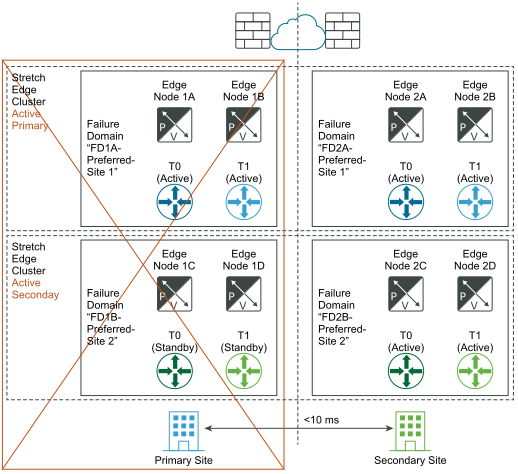
If a failure of one of the Edge nodes in the primary site and not full site failure occurs, it is important that the same principle applies. For example, in the diagram, "Before the disaster", assume that Edge node 1B hosts the tier-1-blue active and that the Edge node 2B hosts the tier-1-blue standby. If Edge node 1B fails, the standby tier-1-blue on the Edge node 2B takes over and become the new tier-1-blue active gateway.
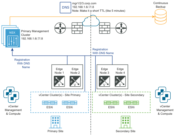
Manual/Scripted Recovery of the Management Plane
- DNS for NSX Manager with a short TTL (for example, 5 minutes).
- Continuous NSX Manager backup.
Neither vSphere HA, nor a stretched management VLAN, is required. NSX Managers must be associated with a DNS name with a short TTL. All transport nodes (Edge nodes and hypervisors) must connect to the NSX Manager using their DNS name. To save time, you can optionally pre-install an NSX Manager cluster in the secondary site.
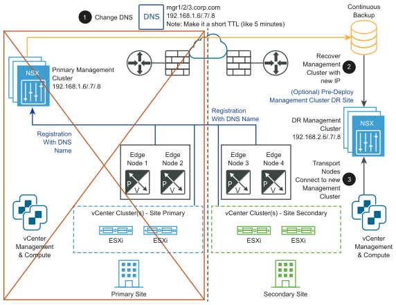
- Change the DNS record so that the NSX Manager cluster has different IP addresses.
- Restore the NSX Manager cluster from a backup.
- Connect the transport nodes to the new NSX Manager cluster.
The following diagrams illustrate manual/scripted recovery of the management plane.
Before the disaster:
After the disaster:
Manual/Scripted Recovery of the Data Plane
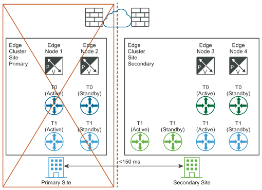
Requirement: The maximum latency between Edge nodes is 150 ms.
The Edge nodes can be VMs or bare metal. The tier-0 gateways in each location can be active-standby or active-active. You can install Edge node VMs in different vCenter Servers. No vSphere HA is required.
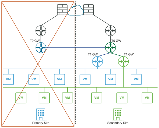
- For all tier-1 in primary site (blue), update their Edge Cluster configuration to be the Edge Cluster Site secondary.
- For all tier-1 in primary site (blue), reconnect them to T0 secondary (green).
The following diagrams illustrate manual/scripted recovery of the data plane with both the logical and physical network views.
Before the disaster (logical and physical views):
After the disaster (logical and physical views):
Requirements for Multisite Deployments
- The bandwidth must be at least 1 Gbps and the latency (RTT) must be less than 150 ms.
- Set the MTU to 9000. It must be at least 1600.
- With automatic recovery of management plane with VLAN management stretched between sites. vSphere HA across sites for NSX Manager VMs.
- With manual/scripted recovery of the management plane with VLAN management stretched between sites. VMware SRM for NSX Manager VMs.
- With manual/scripted recovery of the management plane without VLAN management stretched between sites.
- Continuous NSX Manager backup.
- NSX Manager must be set up to use FQDN.
- The same internet provider must be used if public IP addresses are exposed through services such as NAT or load balancer.
- With automatic recovery of the management plane
- Maximum latency between locations is 10 ms.
- The HA mode for the tier-0 gateway must be active-standby and the failover mode must be preemptive to guarantee no asymmetric routing.
- The HA mode for the tier-0 gateway can be active-active if asymmetric routing is acceptable (such as different buildings in a metropolitan region).
- With manual/scripted recovery of the management plane
- Maximum latency between locations is 150 ms.
- The CMS must support an NSX plug-in. In this release, VMware Integrated OpenStack (VIO) and vRealize Automation (vRA) satisfy this requirement.
Limitations
- No local-egress capabilities. All north-south traffic must occur within one site.
- The compute disaster recovery software must support NSX, for example, VMware Site Recovery Manager 8.1.2 or later.
- When restoring the NSX Manager in a multi-site environment do the following on the secondary/primary site:
- After the restore process pauses at the AddNodeToCluster step, before you add manager nodes you must first remove the existing VIP and set the new virtual IP from the UI page.
- Add new nodes to a restored one-node cluster after the updates to the VIP.
