


To enable access between your VMs and the outside world, you can configure an external or internal BGP (eBGP/iBGP) connection between a tier-0 logical router and a router in your physical infrastructure.
The iBGP feature has the following capabilities and restrictions:
- Redistribution, prefix lists, and routes maps are supported.
- Route reflectors are not supported.
- BGP confederation is not supported.
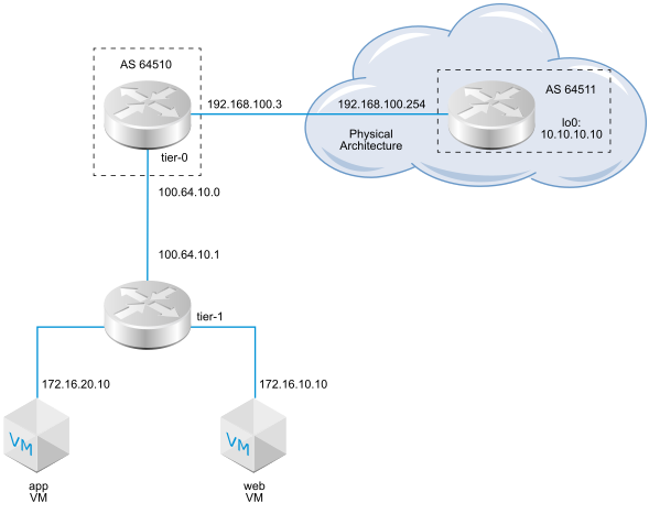
When configuring BGP, you must configure a local Autonomous System (AS) number for the tier-0 logical router. For example, the following topology shows the local AS number is 64510. You must also configure the remote AS number. EBGP neighbors must be directly connected and in the same subnet as the tier-0 uplink. If they are not in the same subnet, BGP multi-hop should be used.
A tier-0 logical router in active-active mode supports inter-SR (service router) routing. If router #1 is unable to communicate with a northbound physical router, traffic is re-routed to router #2 in the active-active cluster. If router #2 is able to communicate with the physical router, traffic between router #1 and the physical router will not be affected.
- In the case of a static route configured on one SR (for example, SR #1 on Edge node #1), another SR (for example, SR #2 on Edge node #2) might learn the same route from an eBGP peer and prefer the learned route to the static route on SR #1, which might be more efficient. To ensure that SR #2 uses the static route configured on SR #1, configure the tier-1 logical router in pre-emptive mode and configure Edge node #1 as the preferred node.
- If the tier-0 logical router has an uplink port on Edge node #1 and another uplink port on Edge node #2, ping traffic from tenant VMs to the uplinks works if the two uplinks are in different subnets. Ping traffic will fail if the two uplinks are in the same subnet.
- With only BGP configured, if all BGP neighbors go down, the service router's state will be down.
- With only BFD configured, if all BFD neighbors go down, the service router's state will be down.
- With BGP and BFD configured, if all BGP and BFD neighbors go down, the service router's state will be down.
- With BGP and static routes configured, if all BGP neighbors go down, the service router's state will be down.
- With only static routes configured, the service router's state will always be up unless the node is experiencing a failure or in a maintenance mode.
Prerequisites
- Verify that the tier-1 router is configured to advertise connected routes. See Configure Route Advertisement on a Tier-1 Logical Router in Manager Mode. This is not strictly a prerequisite for BGP configuration, but if you have a two-tier topology and you plan to redistribute your tier-1 networks into BGP, this step is required.
- Verify that a tier-0 router is configured. See Create a Tier-0 Logical Router in Manager Mode.
- Make sure the tier-0 logical router has learned routes from the tier-1 logical router. See Verify that a Tier-0 Router Has Learned Routes from a Tier-1 Router.
-
Verify that Manager mode is selected in the NSX Manager user interface. See NSX Manager. If you do not see the Policy and Manager mode buttons, see Configure the User Interface Settings.
Procedure
What to do next
Test whether BGP is working properly. See Verify BGP Connections from a Tier-0 Service Router.
