Workloads attached to overlay segments typically communicate at layer 3 with physical devices outside of the NSX domain, through tier-0 gateways instantiated on NSX Edge. However, there are some scenarios where layer 2 connectivity is required between virtual machines in NSX and physical devices.
Some examples are:
Migration from physical to virtual, or virtual to virtual.
Integration of a physical appliance that provides services to a segment, like an external load balancer.
Connection to a database server that requires layer 2 adjacency to its virtual machine clients.
For that purpose, on the top of the gateway service,
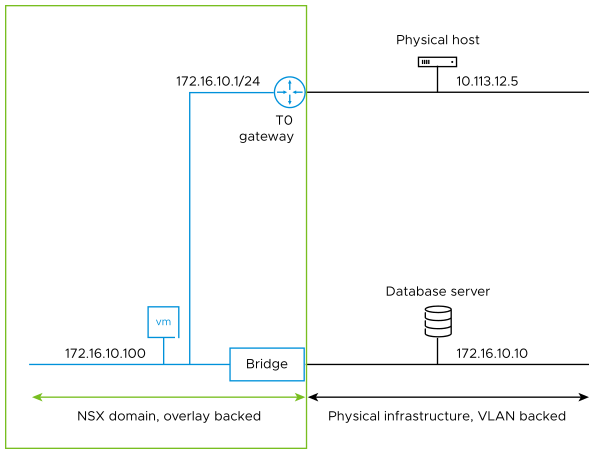
NSX Edge can also run a bridge service. The following diagram represents those two options: the virtual machine in the bottom left corner has layer 3 connectivity through a gateway to the physical host, and layer 2 connectivity through a bridge to the database server. It is possible to both route and bridge a segment. In fact, it is possible to use the tier 0 gateway in this diagram as a default gateway for the database server.
Figure 1. NSX VM Bridge and Gateway Communication
The NSX Edge bridge, like the gateway, is supported for long term deployments, even if it is often used as a temporary solution during migrations.
The bridge functionality extends an overlay segment into a VLAN, identified by a VLAN ID on an uplink of the
NSX Edge where the bridge is running. Typically, two redundant active and standby bridges get deployed on separate edges as part of the same edge cluster. There is no active/active redundancy possible. Setting up the bridge functionality involves the following configuration steps:
Make sure that the NSX Edge is suitable for hosting the bridge service. The bridge adds a few constraints to the deployment of an edge in a VM form factor.
Identify the NSX Edges that run the bridge service. A bridge profile statically designates the edge responsible for running the active bridge and optionally designates a second edge hosting the standby bridge.
Lastly associate an overlay segment to a VLAN ID or IDs and a bridge profile. This results in the creation of the appropriate active/standby bridges on the edges specified in the bridge profile, that extend at layer 2 the overlay segment to the VLAN or VLANs identified by the VLAN IDs.