Ethernet VPN (EVPN) is a standards-based BGP distributed control plane for Network Virtualization Overlay (NVO), that provides Layer 2 (bridging) and Layer 3 (routing) connectivity over IP or IP/MPLS underlay networks. BGP EVPN was initially designed to be used with MPLS data plane to address limitations of VPLS in service provider networks. However, EVPN has been widely adopted in data centers as a control plane mechanism for VXLAN overlay networking due to advantages in BGP scalability and flexibility.
Some of the key characteristics and benefits for BGP EVPN are:
-
BGP-based control plane learning for Layer 2 and Layer 3 end host reachability information. This replaces flood-and-learn behavior of legacy L2VPN solutions, such as VXLAN, SPB, and Trill.
-
ARP suppression to minimize unnecessary ARP and ND message flooding.
-
Support for bridging-only and/or integrated routing and bridging.
-
Support for MAC and IP mobility and multihoming.
MP-BGP EVPN Address Family
A new MP Address Family Indicator/Subsequent Address Family Indicator (AFI/SAFI) is defined for EVPN: l2vpn (25) /evpn (70). For two BGP speakers to exchange EVPN Network Layer Reachability Information (NLRI), they must negotiate the EVPN BGP capability at the start of the BGP session to ensure that both peers can support such NLRI.
Route Distinguisher and Route Targets
BGP EVPN uses the same mechanisms of other BGP VPN technologies to ensure uniqueness and multi-tenancy:
| Mechanism | Description |
|---|---|
| Route Distinguisher (RD) |
|
| Route Target (RT) |
|
EVPN Route Types
EVPN NLRI is further classified by the following route types:
| Route Type | Description | Purpose | NSX Inline Mode | NSX Route Server Mode |
|---|---|---|---|---|
| Type 1 (RT-1) |
Ethernet Auto-Discovery (A-D) route |
Used in data centers to support EVPN active-active of multihoming. |
No |
Yes (receive only for DC-GW mutlihoming) |
| Type 2 (RT-2) |
MAC/IP Advertisement route |
Advertises reachability of a specific MAC address, and optionally MAC and IP address binding. |
No |
Yes |
| Type 3 (RT-3) |
Inclusive Multicast Ethernet Tag route |
Advertises reachability of a VNI associated to a particular VTEP in a virtual network. Type 3 routes are required for BUM traffic delivery across EVPN networks. |
No |
Yes |
| Type 4 (RT-4) |
Ethernet Segment route |
Used in data centers with multihomed endpoints, and used for Designated Forwarder Election to ensure that only one of the VTEPs forwards BUM traffic. |
No |
No |
| Type 5 (RT-5) |
IP Prefix route |
Advertises IPv4 and IPv6 prefixes reachability. This advertisement of prefixes into the EVPN domain provides the ability to build L3VPN similar services. |
Yes |
Yes |
| Type 6 (RT-6) |
Selective Multicast Ethernet Tag route |
Used to advertise the intent of the host or VM to receive multicast traffic for a certain Multicast Group (*,G) or Source-Group combination (S,G). |
No |
No |
Virtual Routing and Forwarding
Virtual routing and forwarding (VRF) makes it possible to instantiate isolated routing and forwarding tables within a router. These routing and forwarding table instances isolate Layer 3 domains and segments from each other creating a multi-tenant network, either locally within the router or across multiple routers.
VRFs are supported in NSX by deploying tier-0 VRF gateways. A tier-0 VRF gateway must be linked to a parent tier-0 gateway and inherits some of the tier-0 settings, such as the HA mode, edge cluster, internal transit subnet, T0-T1 transit subnets, and BGP local ASN.
Multiple tier-0 VRF gateways can be created under the same parent tier-0, allowing the separation of segments and tier-1 gateways into multiple isolated tenants. With tier-0 VRF gateways, tenants can use overlapping IP addresses without any interference or communication with each other.
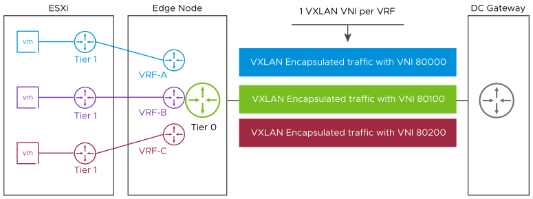
In the context of EVPN, each Layer 3 VRF is identified by a global unique Virtual Network Identifier (VNI). The VNI for each VRF must match in NSX Edge nodes and data center gateways.
VXLAN Encapsulation and VNI
VXLAN encapsulation as defined in RFC7348, is used between NSX tunnel endpoints (edge nodes for Inline mode and hypervisors for Route Server mode) and external routers in order to ensure data plane compatibility with other vendors. Inside the NSX domain, GENEVE encapsulation is still used.
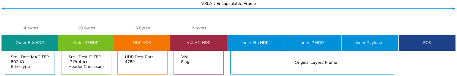
The VNI is a 24-bit identifier used to identify a particular virtual network segment. When EVPN is used to advertise IP prefixes reachability by using Route Type 5 and the encapsulation type as VXLAN then the VNI identifies the tenant VRF instance. As defined in RFC9135, this VNI is advertised in the BGP control plane along with the prefix routes as well as used in the data plane encapsulation to differentiate the traffic between VRFs. The VNI for each VRF must match in NSX Edge nodes and data center gateways.