


In the some of the supported Windows physical server topoplogies you can pre-configure teaming in the Windows OS before deploying NSX, while in other supported topolgies you can configure teaming in NSX and then deploy NSX.
Supported Topologies: Pre-configured NIC Teaming on Windows Physical Server
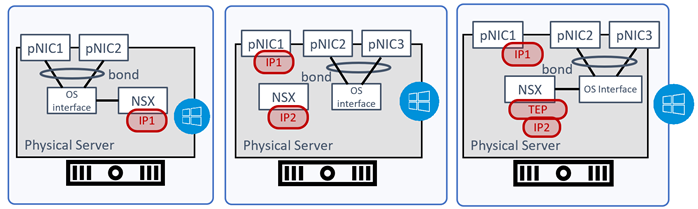
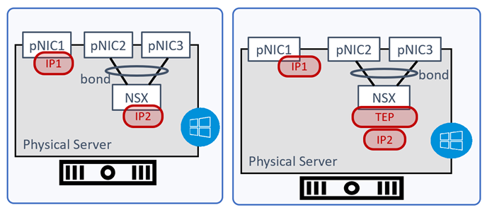
Topology1:
- Configured pNIC1 and pNIC2 as bonding interface in Windows OS.
- Use IP1 on NSX for VLAN traffic.
Topology 2:
- Configured pNIC2 and pNIC3 as bonding interface in Windows OS.
- Use IP1 on pNIC1 for management traffic on the host.
- Use IP2 on NSX for VLAN traffic.
Topology 3:
- Configured pNIC2 and pNIC3 as bonding interface in Windows OS.
- Use IP1 on pNIC1 for management traffic on the host.
- Use IP2 as TEP on NSX for overlay traffic.
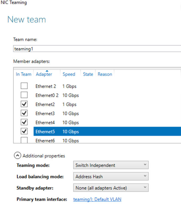
Windows NIC Teaming Configured with Active-Standby Adapters
- In the Windows OS interface, create a NIC team teaming1 with Ethernet2, Ethernet3,Ethernet4, Ethernet5 as the NIC members and set the Teaming Mode to Switch Independent.
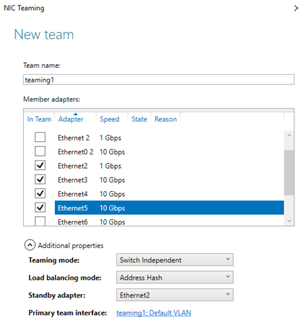
- On the NIC teaming window, set the Load balancing mode to Address Hash. You can also set the mode to IP Addresses or MAC Addresses.
Note: To set IP Addresses and Mac Addresses as the Load balancing mode, open a PowerShell session and run Set-NetLbfoTeam.
- Set one of the ethernet members as the standby adapter. For example, set Ethernet2 as the standby member.
- From a browser window, open the NSX Manager UI interface.
- Go to .
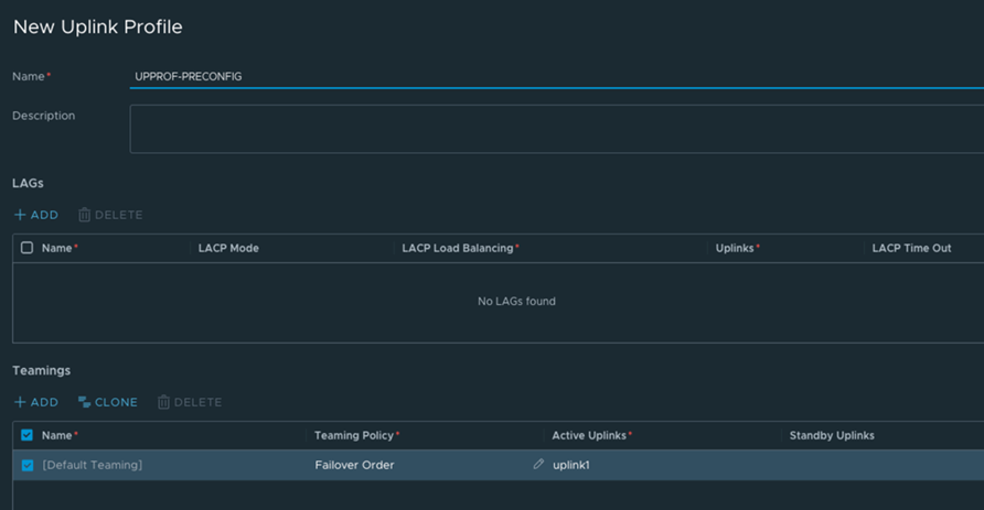
- Create a new uplink profile, such as, UPPROF-PRECONFIG and use the default teaming policy with Active Uplink set to the Teaming interface, uplink1.
- To prepare the Windows Host as a transport node, go to .
- Select the Windows physical server and click Configure NSX.
- In the Add Host Switch configuration window, select the uplink profile to UPPROF-PRECONFIG.
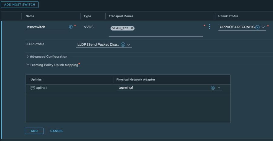
- In the Teaming Policy Uplink Mapping section, set the uplink1 teaming interface to the physical network adapter, teaming1. You are using the NIC teaming, teaming1, set in the Windows OS that you configured at the beginning of the procedure. The NIC teaming comprises of the bond of Ethernet2, Ethernet3, Ethernet4, and Ethernet5.
- Proceed with deployment of the Windows physical server host as a transport node.
Windows NIC Teaming Configured with Active/Active Adapters
- In the Windows OS interface, create a NIC team teaming1 with Ethernet2, Ethernet3, Ethernet4, and Ethernet5 as the NIC members and set the Teaming Mode to Switch Independent.
- On the NIC teaming window, set the Load balancing mode to Address Hash. You can also set the mode to IP Addresses or MAC Addresses.
Note: To set IP Addresses and Mac Addresses as the Load balancing mode, open a PowerShell session and run Set-NetLbfoTeam.
- On the NIC teaming window, set the standby adapter to None. All NIC members are active in this configuration.
- From a browser window, open the NSX Manager UI interface.
- Go to .
- Create a new uplink profile, UPPROF-PRECONFIG and use the default teaming policy with Active Uplink set to the Teaming interface, uplink1.
- To prepare the Windows Host as a transport node, go to .
- Select the Windows physical server and click Configure NSX.
- In the Add Host Switch configuration window, select the uplink profile to UPPROF-PRECONFIG.
- In the Teaming Policy Uplink Mapping section, set the uplink1 teaming interface to the physical network adapter, teaming1. You are using the NIC teaming, teaming1, set in the Windows OS that you configured at the beginning of the procedure. The NIC teaming comprises of the bond of Ethernet2, Ethernet3, Ethernet4, and Ethernet5.
- Proceed with deployment of the Windows physical server host as a transport node.
Supported Topologies: NSX Configured NIC Teaming on Windows Physical Server
In the following topologies you configure NIC teaming bond interface in the NSX UI and then deploy NSX on the Windows physical server.
Topology 1:
- Configured pNIC2 and pNIC3 as bonding interface in NSX.
- Use IP2 on NSX for VLAN traffic.
- Use IP1 for management traffic on the host.
Topology 2:
- Configured pNIC2 and pNIC3 as bonding interface in NSX.
- Use IP2 for TEP on NSX for overlay traffic.
- Use IP1 for management traffic on the host.
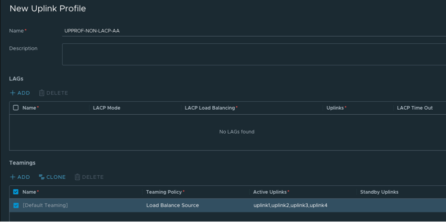
NSX Configured NIC Teaming Without LACP
In this configuration, you create an uplink profile using the default teaming policy as Active-Standby or Active-Active without configuring LACP profile along with the teaming policy.
- From a browser window, open the NSX Manager UI interface.
- Go to .
- Create a new uplink profile, UPPROF-NON-LACP-AA and you can use the Teaming Policy as Failover or Load Balance Source.
- The Active Uplinks field can be set to multiple uplinks, for example, uplink1, uplink2, uplink3, uplink4. These uplinks will be mapped later during transport node configuration to the Ethernet adapters on the Windows physical server.
- To prepare the Windows Host as a transport node, go to .
- Select the Windows physical server and click Configure NSX.
- In the Add Host Switch configuration window, select the uplink profile to UPPROF-NON-LACP-AA.
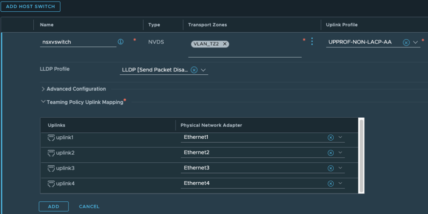
- In the Teaming Policy Uplink Mapping section, map uplink1 to Ethernet1, uplink2 to Ethernet2, uplink3 to Ethernet3, uplink4 to Ethernet4.
- Deploy the Windows physical server as a transport node. The deployed transport node will be configured to carry traffic using the ethernet adapters that are mapped the uplinks in the host switch.
NSX Configured NIC Teaming With LACP
In this configuration, you create an uplink profile using the default teaming policy as Active-Active with LACP configuration.
- From a browser window, open the NSX Manager UI interface.
- Go to .
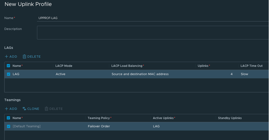
- Create a new uplink profile, such as, UPPROF-LAG.
- Create a LAG profile, such as LAG, LACP mode to Active and the LACP Load Balancing mode to Source and Destination MAC address.
- Use the Teaming Policy as Failover and set the Active Uplink to LAG.
- These uplinks will be mapped later during transport node configuration to the Ethernet adapters on the Windows physical server.
- To prepare the Windows Host as a transport node, go to .
- Select the Windows physical server and click Configure NSX.
- In the Add Host Switch configuration window, select the uplink profile to UPPROF-LAG.
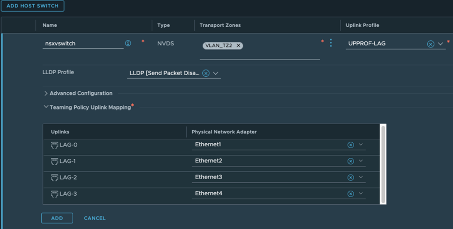
- In the Teaming Policy Uplink Mapping section, map LAG-0 to Ethernet1, LAG-1 to Ethernet2, LAG-2 to Ethernet3, LAG-3 to Ethernet4.
- Deploy the Windows physical server as a transport node. The deployed transport node will be configured to carry traffic using the ethernet adapters that are mapped the uplinks in the host switch.
