As a VI administrator working in the vSphere environment, you can configure NSX for virtual networking. The workflow involves configuring logical segments to establish connectivity between hosts even in different subnets, configuring NSX Edge nodes, Tier-0 gateways, Tier-1 gateways and segments. Finally, workload VMs connected to these segments can pass north-south and east-west traffic.
Prerequisites
- Ensure that ESXi hosts are compatible with VMware vCenter version v7.0.3 or later.
- Ensure that VMware vCenter version is v7.0.3 or later.
- Configure a vSphere Distributed Switch (VDS) switch on hosts. Only VDS 6.6 or later is supported.
- On a vSphere Lifecycle Manager enabled cluster, edit the VMware vCenter from the NSX Manager UI to:
Procedure
- From a browser, log in with admin privileges to an VMware vCenter at https://<vcenter-server-ip-address>.
- On the vSphere Client UI, select vSphere Client menu and click NSX.
- On the Welcome to NSX screen, on the Virtual Networking card, click Getting Started.
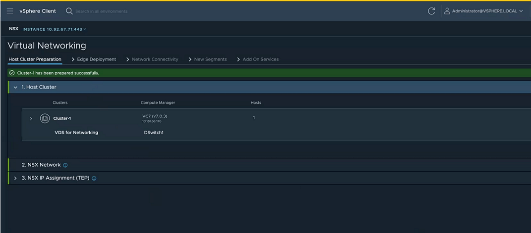
- In the Host Cluster Preparation tab, perform the following tasks.
- Expand the Host Cluster section, select the clusters that you want to prepare for virtual networking and click Next.
Note: Any cluster with an incompatible ESXi host is not allowed for host preparation.
- Expand the NSX Network section, enter a VLAN ID that will tag the overlay traffic and click Next.
- Expand the NSX IP Assignment (TEP) section, and enter IP details:
| Field |
Description |
| IP Assignment |
Select the mode of IP assignment, from between static and DHCP. If you select IP pool, enter a name for the pool, IP range, subnet along with prefix (subnet/prefix) and default gateway. NSXe does not support the IPv6 address type to be assigned as a TEP IP address of a host. |
- Click Prepare Cluster to begin installation of NSX.
Cluster preparation begins. View installation progress at each host.
Alternatively, you can also verify the progress in NSX Manager UI. NSX creates a new transport node profile using the configuration that you defined in the installation section. The switch is set to VDS. The transport node profile is applied to the cluster to prepare hosts of the cluster as transport nodes.
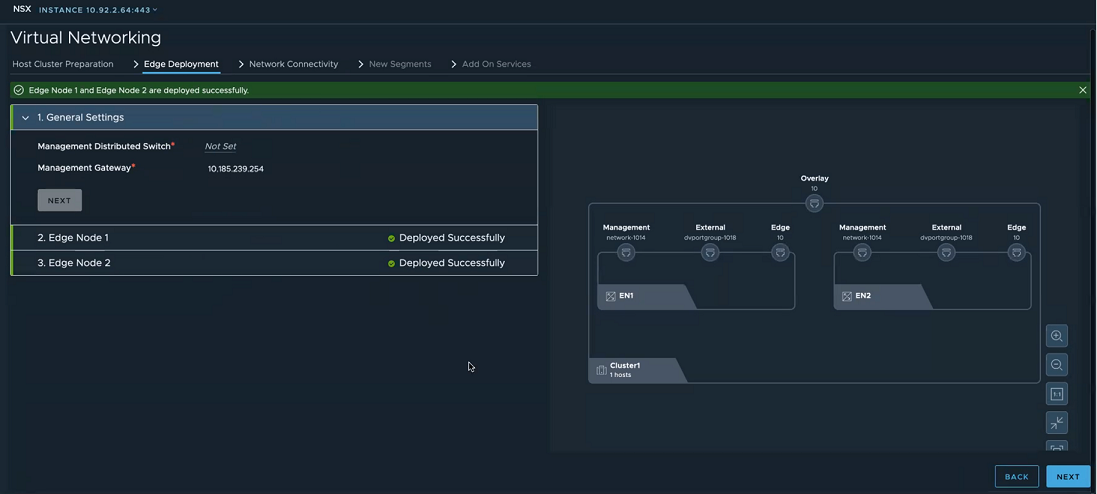
- In the Edge Deployment tab, expand the Management Network for Edge Connectivity and enter the following details:
| Field |
Description |
| Management VDS |
Select a vSphere Distributed Switch for management traffic on NSX Edge nodes. |
| Management Network |
Select a network for management traffic of NSX Edge nodes. |
| Management Gateway |
Select the gateway to route management traffic. Enter a static IP address. |
- Click Next.
- In the Edge Deployment tab, expand the Edge Node 1 and enter the following details
| Field |
Description |
| Name |
Enter a name for the Edge node. |
| Fully Qualified Domain Name |
Enter a Fully Qualified Domain Name that resolves to the IP address of the NSX Edge node. |
| Management IP address |
Enter an IP address for management traffic of the NSX Edge node. |
| External Network Connectivity |
Select a distributed port group to be used as a data path interface. This distributed port group manages the ingress and egress traffic of workload VMs that are processed by the NSX Edge node.
Note: Even though there are three data path interfaces on an
NSX Edge node, this workflow uses only one interface for a distributed port group.
|
| Edge Node Settings |
Select Apply same settings for all Edges if you want to replicate the settings across all NSX Edge nodes. |
| Password |
Enter a password that conforms to the required password complexity. Additionally, the password length must not exceed 128 characters. Enter the same password in the next field. |
| Virtual Machine Size |
Select a form factor to deploy the Edge node. |
| Storage Location |
Select the datastore as storage location for installation and configuration files and data generated by the Edge node. |
- On the Edge Deployment tab, verify that the visualization is updated with management network, external network and other details related to NSX Edge node.
- Enter details for Edge Node 2.
- Click Deploy Edge.
- On the confirmation window, click Deploy.
- Observe the topology created based on the configuration details entered on the Edge Deployment tab. After NSX Edge nodes are realized, the dotted line turns to a solid line, indicating NSX Edge node is realized.
- Click Next to configure network connectivity.
- In the Network Connectivity tab, expand the Physical Router section and enter the following details:
| Field |
Description |
| Do you want to peer with a physical router now? |
After deploying the NSX Edge node, it can establish a peer connection with a physical router.
- Select Yes if you want to set up Border Gateway Protocol (BGP) or static routing to your physical router.
- BGP Local AS: Enter the local autonomous system number for use in BGP.
- Select No if you do not want to set up BGP or static routing to your router. However, you will need to set up NAT to connect to workloads to external networks.
- In the Physical Routing IP address field, enter a static IP address.
|
| How many physical routers do you want to peer with? |
Based on your selection, enter the following details for one or two physical routers: If you want to allow other routers to peer with your router, then enter the following details: For each peer router, enter these details:
- BGP Local AS: Enter the local autonomous system number used by the BGP neighbor.
- BGP Neighbors:
- IP Address: Enter the IP address of the physical router, which is the BGP neighbor.
- Remote AS: Remote autonomous system number used by BGP neighbors.
|
- Click Next.
- In the Network Connectivity tab, expand the NSX Gateway section and enter the following details:
| Field |
Description |
| Gateway Name Prefix |
Enter a prefix for the gateway. Every object, such as Tier-0, Tier-1 gateways, that are created for the gateway is prefixed with this value. You can search for objects with a specific prefix to get a list of objects related to a particular gateway. |
| Uplink VLAN for Router 1 |
Enter the VLAN ID to tag VLAN traffic going from NSX Edge node to physical router 1. |
| Uplink VLAN for Router 2 |
Enter the VLAN ID to tag VLAN traffic going from NSX Edge node to physical router 2. |
- Click Next.
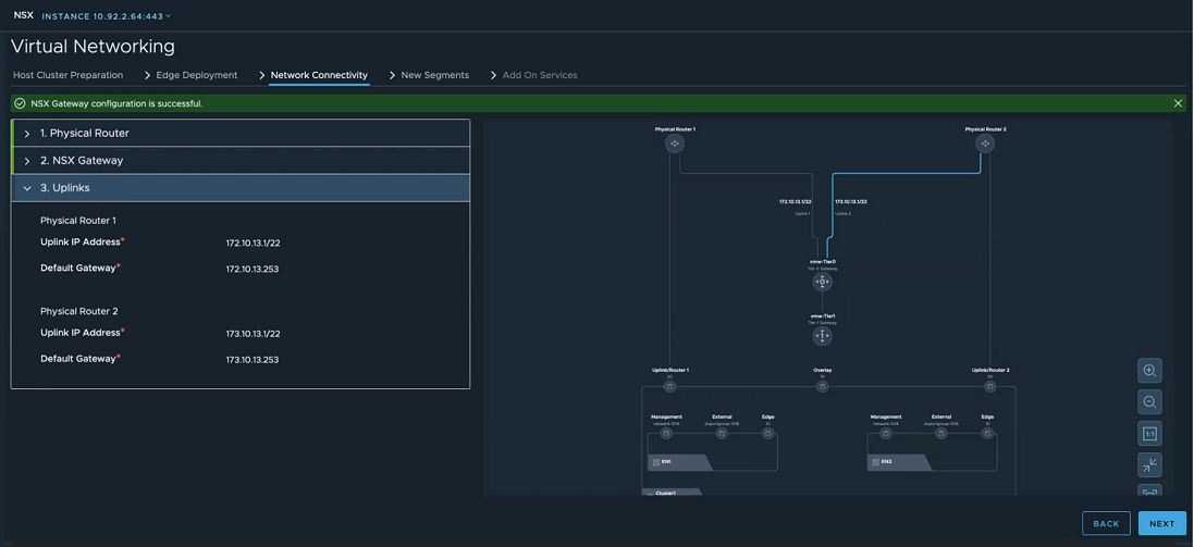
- In the Network Connectivity tab, expand the Uplinks section and enter the following details:
| Field |
Description |
| IP Address for Uplink 1 |
Enter the IP address for uplink from NSX gateway or Tier-0 gateway to physical router 1. |
| IP Address for Uplink 2 |
Enter the IP address for uplink from NSX gateway or Tier-0 gateway to physical router 2. |
| Physical Router 1 |
Enter subnet mask and default gateway for physical router 1. |
| Physical Router 2 |
Enter subnet mask and default gateway for physical router 2. |
- Verify the visualization created based on the network details you entered.
- Click Create Gateways.
- On the confirmation window, click Create Gateways.
The NSX Gateway is successfully created.
- In the New Segments tab, create a segment where workloads VMs will be running. For example, create a segment for a web group. Enter the following details:
| Field |
Description |
| Name |
Enter the name of the segment. |
| Subnet/Prefix Length |
Enter the subnet network for the segment. |
| Default Gateway |
Enter the default gateway that segments should forward traffic to. |
- To create additional segments, click Add Segment and enter the required details.
- Click Create Segment.
- After segments are created, add them to NSX distributed virtual port group.
- Click Next.
- (Optional) In the Add-on Services tab, enter Network Address Translation (NAT) details. On the NAT Only window, enter the following details:
| Field |
Description |
| Name |
Enter a name for NAT service. |
| Source |
Select a segment so that IP addresses of local hosts connected to this segment are translated and protected and a single translated IP address is presented to an external network. |
| Translated |
The IP address that is presented to external network thus protecting local hosts from exposing their IP addresses to an external network. |
- Click Next.
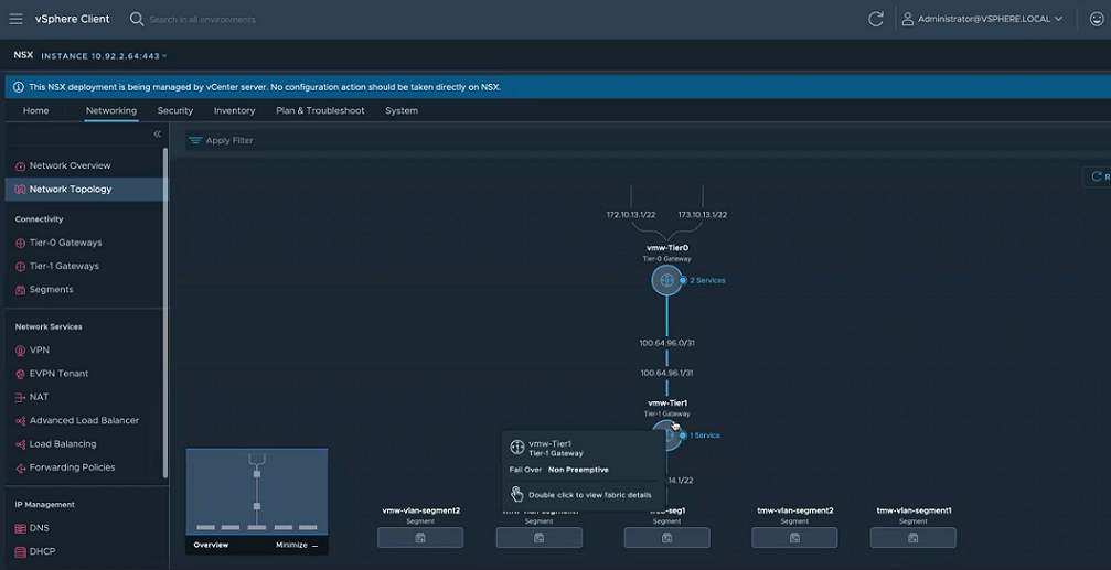
- View the created topology created in NSX.
Results
NSX is configured for virtual networking.
What to do next
- From a browser log in to NSX Manager with https://<NSX Manager-IP-Address>/.
- After logging in to NSX Manager, verify networking configuration is successfully created in NSX.


 The NSX Gateway is successfully created.