An uplink is a link from the NSX Edge nodes or hypervisor nodes to the top-of-rack switches or NSX logical switches. A link is from a physical network interface on an NSX Edge node or hypervisor nodes to a switch.

An uplink profile defines policies for the uplinks. The settings defined by uplink profiles can include teaming policies, active and standby links, transport VLAN ID, and MTU setting.

Consider the following points when configuring Failover Teaming Policy for VM appliance-based NSX Edge nodes and Bare Metal NSX Edge:
  • For uplinks used by a teaming policy, you cannot use he same uplinks in a different uplink profile for a given NSX Edge transport node. Standby uplinks are not supported and must not be configured in the failover teaming policy. If the teaming policy uses more than one uplink (active/standby list), you cannot use the same uplinks in the same or a different uplink profile for a given NSX Edge transport node.
  • Supported scenarios:
    • Bare Metal NSX Edge supports a single active uplink and a standby uplink. They do not support multiple standby uplinks.
    • NSX Edge VMs do not support any standby uplinks - single or multiple standby uplinks.
Consider the following points when configuring Load Balance Source for VM appliance-based NSX Edge nodes:
  • Supports multiple active uplinks.
  • You cannot use LAG to configue the teaming policy.
  • In the Active Uplinks field, enter uplink labels that will be associated to physical NICs when you prepare transport nodes. For example, uplink1, uplink2. When you prepare transport nodes, you will associate uplink1 to pnic1 and uplink2 to pnic2.
  • You must use the Load Balanced Source teaming policy for traffic load balancing.

Consider the following points when configuring Load Balance Source for Bare Metal NSX Edge:

  • Supports multiple active uplinks.
  • In the Active Uplinks field, you can use LAGs or enter individual uplink lables. For example, LAG1 or uplink1, uplink2.
  • A LAG must have two physical NICs on the same N-VDS.
  • The number of LAGs that you can actually use depends on the capabilities of the underlying physical environment and the topology of the virtual network. For example, if the physical switch supports up to four ports in an LACP port channel, you can connect up to four physical NICs per host to a LAG.
  • In the LACP section, Bare Metal NSX Edge only supports Source and destination MAC address, IP address and TCP/UDP port.
  • If multiple LAG uplinks are configured on a Bare Metal NSX Edge, enter a unique LAG name for each LAG uplink profile.
  • If multi-vtep uplink profile is used for Bare Metal NSX Edge or edge VMs, NSX only supports Load Balance Source teaming policy.
  • You must use the Load Balanced Source teaming policy for traffic load balancing.

Prerequisites

  • See NSX Edge network requirements in NSX Edge Installation Requirements.
  • Each uplink in the uplink profile must correspond to an up and available physical link on your hypervisor host or on the NSX Edge node.

    For example, your hypervisor host has two physical links that are up: vmnic0 and vmnic1. Suppose vmnic0 is used for management and storage networks, while vmnic1 is unused. This might mean that vmnic1 can be used as an NSX uplink, but vmnic0 cannot. To do link teaming, you must have two unused physical links available, such as vmnic1 and vmnic2.

    For an NSX Edge, tunnel endpoint and VLAN uplinks can use the same physical link. For example, vmnic0/eth0/em0 might be used for your management network and vmnic1/eth1/em1 might be used for your fp-ethX links.

Procedure

  1. From a browser, log in with admin privileges to an NSX Manager at https://<nsx-manager-ip-address> or https://<nsx-manager-fqdn>.
  2. Select System > Fabric > Profiles > Uplink Profiles > Add Profile.
  3. Complete the uplink profile details.
    Option Description
    Name and Description Enter an uplink profile name.

    Add an optional uplink profile description.

    LAGs (Optional) In the LAGs section, click Add for Link aggregation groups (LAGs) using Link Aggregation Control Protocol (LACP) for the transport network.

    The active and standby uplink names you create can be any text to represent physical links. These uplink names are referenced later when you create transport nodes. The transport node UI/API allows you to specify which physical link corresponds to each named uplink.

    Possible LAG hashing mechanism options:

    • Source MAC address
    • Destination MAC address
    • Source and destination MAC address
    • Source and destination IP address and VLAN
    • Source and destination MAC address, IP address, and TCP/UDP port

    Supported LAG hashing mechanisms on hosts types:

    • NSX Edge nodes: Source and destination MAC address, IP address, and TCP/UDP port.
    • ESXi hosts with VDS in Enhanced Networking Stack (ENS) mode: Source MAC address, Destination MAC address, and Source and destination MAC address.

    • ESXi hosts with VDS in Standard mode: Source MAC address, Destination MAC address, Source and destination MAC address, and Source and destination IP address and VLAN.

    • ESXi hosts with vSphere Distributed Switch (v 7.0 and later that supports NSX): LACP is not configured in NSX. You need to configure it in VMware vCenter.

    • Physical server hosts: Source MAC address.

    Teamings
    In the Teaming section, you can either enter a default teaming policy or you can choose to enter a named teaming policy that is only applicable to VLAN networks. Click Add to add a naming teaming policy. A teaming policy defines how VDS uses its uplink for redundancy and traffic load balancing. You can configure a teaming policy in the following modes:
    • Failover Order: Specify an active uplink along with an optional list of standby uplinks. If the active uplink fails, the next uplink in the standby list replaces the active uplink. No actual load balancing is performed with this option. Standby uplinks and multiple active uplinks are not supported for NSX Edge transport nodes. Also, for an NSX Edge transport node, active uplink used in one profile should must not be used in another profile.
    • Load Balance Source: Maps a virtual interface of a VM to an uplink. Traffic sent by this virtual interface will leave the host through this uplink only, and traffic destined to this virtual interface will necessarily enter the virtual switch through this uplink. Select a list of active uplinks. When you configure a transport node, you can pin each interface of the transport node to one active uplink. This configuration allows use of several active uplinks at the same time. No standby uplink is configured in this case.
      Important: To manage VLAN traffic, if you configure a default teaming policy in Load Balance Source mode, then on failure of the first uplink, traffic will not fail over to the second uplink interface.
    • Load Balance Source MAC Address: Select an uplink based on a hash of the source Ethernet. NSX Edge transport nodes do not support this teaming policy.
    Note:
    • On hypervisor hosts:
      • ESXi hosts: Default teaming policies - Load Balance Source MAC, Load Balance Source, and Failover Order teaming policies are supported.
      • Physical server hosts (Linux): Only Failover Order teaming policy is supported. Load Balance Source and Load Balance Source MAC teaming policies are not supported.
      • Physical server hosts (Windows): Supports Load Balance Source and Load Balance Source Mac teaming policies. Load Balance Source teaming policy on NSX is mapped to Address Hash on Windows. Load Balance Source Mac Address on NSX is mapped to Mac Addresses on Windows.
    • On NSX Edge: For default teaming policy, Load Balance Source and Failover Order teaming policies are supported. For named teaming policy, only Failover Order policy is supported.
    ( ESXi hosts and NSX Edge) You can define the following policies for a transport zone:
    • A Named teaming policy for every VLAN-based logical switch or segment.
    • A Default teaming policy for the entire VDS.

    Named teaming policy: A named teaming policy means that for every VLAN-based logical switch or segment, you can define a specific teaming policy mode and uplinks names. This policy type gives you the flexibility to select specific uplinks depending on the traffic steering policy, for example, based on bandwidth requirement.

    • If you define a named teaming policy, VDS uses that named teaming policy if it is attached to the VLAN-based transport zone and finally selected for specific VLAN-based logical switch or segment in the host.
    • If you do not define any named teaming policies, VDS uses the default teaming policy.

    For more details, see Configure Named Teaming Policy.

  4. Enter a Transport VLAN ID value. The transport VLAN set in the uplink profile tags overlay traffic only and the VLAN ID is used by the Tunnel Endpoint Pools (TEP IP Pools).
    Important: While you can choose any of the available pre-created default uplink profiles, note that you can only edit and configure the transport VLAN ID field to a value of your choice. You cannot edit any other field of a pre-created default uplink profile.
  5. Enter the MTU value.
    For hosts that use vSphere VDS, configure MTU on the VDS from VMware vCenter. The uplink profile MTU default value is 1700 bytes and is applicable to transport-nodes that use N-VDS.
    Note: The MTU field is optional. If you do not configure it, NSX takes the value set in the Tunnel Endpoint MTU field. If both MTU fields are set, uplink profile MTU value ovrerrides the tunnel endpoint MTU value.

    Global Fabric Settings

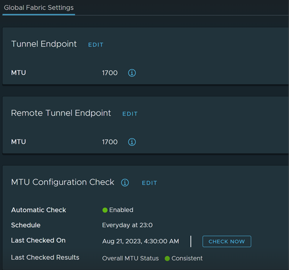
    For more information on MTU guidance, see Guidance to Set Maximum Transmission Unit.

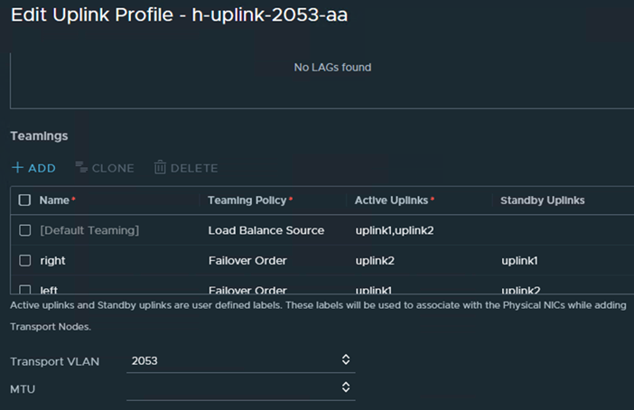
    An example of Active/Active uplink profile for ESXi host with named-teaming (optional) Uplink Profile

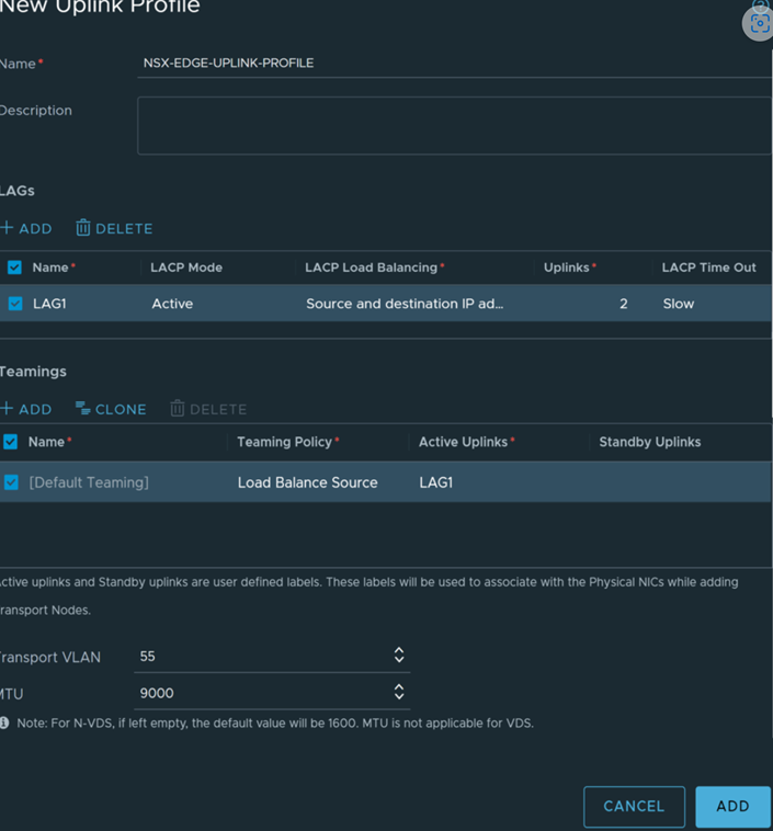
    An example of uplink profile using LAG for ESXi host

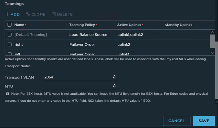
    An example of uplink profile for NSX Edge with named-teaming policy

  6. Configure global tunnel endpoint MTU.

Results

In addition to the UI, you can also view the uplink profiles with the API call GET /policy/api/v1/infra/host-switch-profiles.