


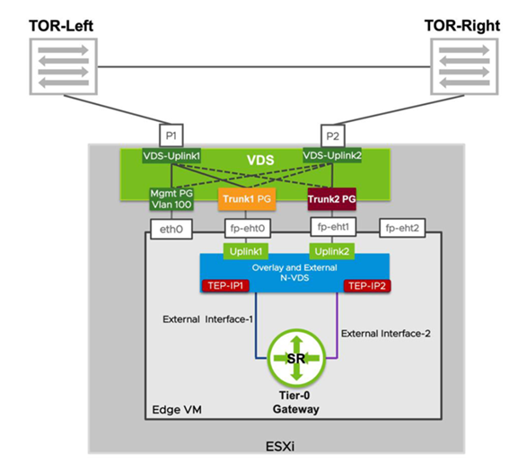
Configure an NSX Edge VM with an N-VDS switch to carry both overlay and external traffic.
In this topology, NSX Edge VM is configured with an N-VDS switch to carry overlay and external traffic.
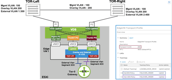
In this topology, the uplink profile attached is configured to use Multi-TEP to provide load balancing for overlay traffic by selecting default teaming to be Load Balancing Source teaming policy with active 'uplink1' and 'uplink2' on transport VLAN 200.
(optional) The uplink profile attached is also configured to use named teaming policy, where 'vlan300-policy' is mapped to uplink1 and 'vlan400-policy' is mapped to uplink2.
To create the topology, follow these steps.
Prerequisites
Procedure
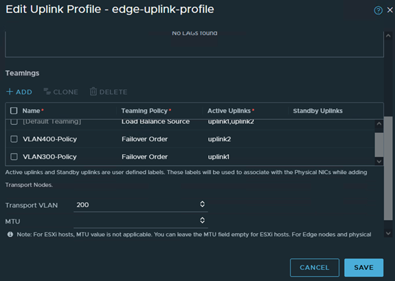
- Uplink Profile creation with named-teaming policy for VLAN networks and default teaming for overlay networks. If named-teaming does not exist in uplink profile then default teaming is used for all networks.
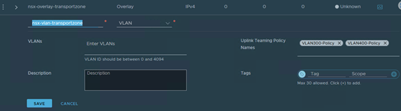
- VLAN Transport Zone is created or modified to use named teaming policy VLAN300-Policy and VLAN400-Policy (if using named-teaming policy).
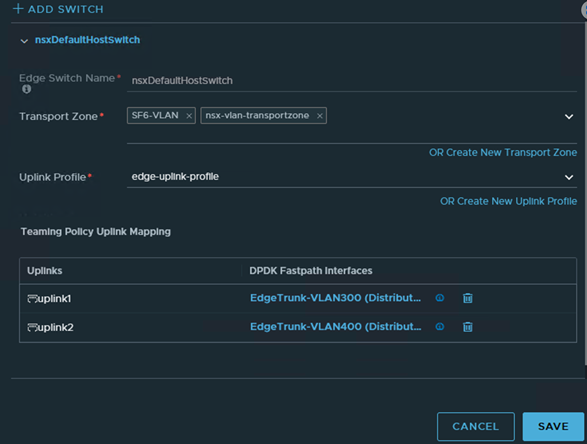
- In the NSX Edge configuration, “Uplink1” (fp-eth0) is vNIC2 on Edge VM and is mapped to use VLAN 300 Trunk PG and “Uplink2”(fp-eth1) is vNIC3 on Edge VM and is mapped to use VLAN 400 Trunk portgroup.
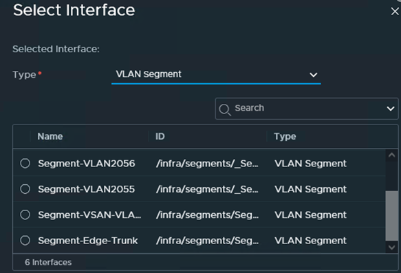
- NSX Edge VM interfaces can connect to VDS Portgroups in vCenter or NSX VLAN Segments.
Note: If Edge interfaces will be connecting to NSX VLAN Segments, ESXi Hosts (hosting the Edge VMs) should be configured as Host Transport Nodes and member of VLAN transport zone.
An example of connecting VM interfaces to NSX VLAN segments.
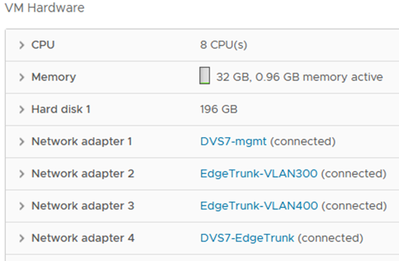
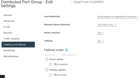
An example of an NSX Edge VM with interfaces on VMware vCenter VDS Edge Trunk Portgroups
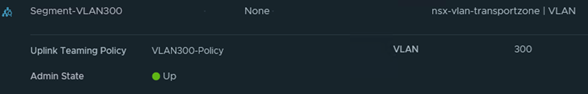
- If VM interfaces connect to NSX VLAN segments, named-teaming is enabled on the segments. The diagram shows that External VLAN segment 300 is configured to use a named teaming policy “Vlan300-Policy” that sends traffic from this VLAN on “Uplink1” (vNIC2 of Edge VM). "External VLAN segment 400" is configured to use a named teaming policy “Vlan400-Policy” that sends traffic from this VLAN on “Uplink2” (vNIC3 of Edge VM).
- If VM interfaces connect to VDS Portgroups in VMware vCenter, then “Trunk1 PG” is configured to use active uplink as “VDS-Uplink1” and standby uplink as “VDS-Uplink2”. “Trunk2 PG” is configured to use active uplink as “VDS-Uplink2” and standby uplink as “VDS-Uplink1”. This configuration ensures that the traffic sent on “External VLAN Segment 300”uses vNIC2 of Edge VM to exit the Edge VM and then “VDS-Uplink1” and is sent to the left TOR switch. Similarly, traffic sent on VLAN 400 uses “VDS-Uplink2” and is sent to the TOR switch on the right.
 Important:
- ESXi TEP and Edge TEP share the same VLAN: Use this configuration only if NSX Edge Trunk 1 portgroup and NSX Edge Trunk 2 portgroup are created from NSX as VLAN segments. Because any traffic between the Edge TEP to its own hypervisor’s TEP does not need to exit the hypervisor.
- ESXi TEP and Edge TEP use different VLANs: Use this configuration if NSX EdgeTrunk1 portgroup and NSX EdgeTrunk2 portgroup are created as VDS portgroups from VMware vCenter. Any traffic between the NSX Edge TEP and its hypervisor TEP must exit the ESXi. The top of rack switch must then route it back toward the ESXi.
- If VM interfaces connect to NSX VLAN segments, named-teaming is enabled on the segments. The diagram shows that External VLAN segment 300 is configured to use a named teaming policy “Vlan300-Policy” that sends traffic from this VLAN on “Uplink1” (vNIC2 of Edge VM). "External VLAN segment 400" is configured to use a named teaming policy “Vlan400-Policy” that sends traffic from this VLAN on “Uplink2” (vNIC3 of Edge VM).
