Add the networking components to create the logical network topology in the NSX. You can create the same logical topology as your existing NSX-V or create a new topology, if necessary.
You must also pre-configure the networking services that are required for your applications to run before the VMs are moved to the new NSX.
The following procedure outlines the workflow for creating the NSX logical topology. For a detailed information about creating and configuring the networking objects, see the NSX Administration Guide. If you plan to create the topology using APIs, see the NSX API Guide for more information.
Procedure
Add tier-0 and tier-1 gateways depending on the requirements of your NSX network topology.
Add NSX overlay segments with the same subnet address as the Logical Switches in NSX-V. Similarly, add NSX VLAN segments with the same subnet address as the Distributed Virtual Port Group (DVPG) VLANs in NSX-V.
The same subnet address helps in ensuring that the IP addresses of the workload VMs are retained after the VMs move to
NSX segments.
You must create the segments with the SOURCE replication mode, and change the mode to MTEP only after the migration is done.
To migrate Distributed Firewall configuration from your NSX-V environment, ensure that the following requirements are met:
The overlay segments in NSX must have the same virtual network identifier (VNI) as the Logical Switches in NSX-V. You must use the NSX APIs to create the overlay segments. You cannot create overlay segments with the same VNI in the NSX Manager UI.
The VLAN segments in NSX must have the same VLAN IDs as the VLAN Distributed Virtual Port Groups in NSX-V.
Note: VLAN Distributed Virtual Port Group must be associated only with a VLAN ID. VLAN Trunk is not supported.
If Layer 3 services such as Network Address Translation, Load Balancing, VPN, and so on, are configured on your NSX-V Edge Services Gateway, configure equivalent services on the tier-1 or tier-0 gateway of your NSX environment. Make sure that both steps 4 and 5 are done.
If Layer 3 services are not configured, skip steps 4 and 5 and proceed directly to step 6.
Caution: Be careful not to enable route advertisement and Layer 3 services on the tier-1 gateway while the north-south traffic is being routed through the Edge Services Gateway. It can conflict with the
NSX-V environment. Also, remember that your workload VMs are not yet moved to
NSX. The best time to enable route advertisement and Layer 3 network services is when you are ready to switch the default gateway for north-south traffic to the
NSX side.
In NSX Manager, navigate to Networking > Tier-1 Gateways.
Click the vertical ellipses next to the tier-1 gateway, and then click Edit.
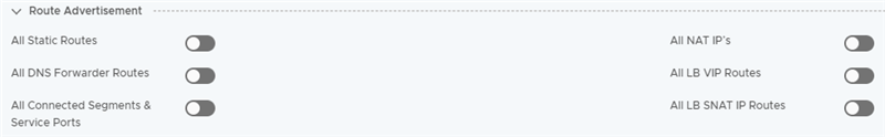
Expand the Route Advertisement section, and turn off all the toggle buttons for the L3 services.
For example:
Connect the uplink interface of the tier-0 gateway to a transit VLAN segment.
Optionally, configure dynamic route peering between tier-0 gateway and the north-facing physical routers. If you configure dynamic routing, ensure that
Route Redistribution Status is turned off on the tier-0 gateway so that no subnets are advertised in the
NSX environment. You must enable
Route Redistribution Status when you are ready to switch the default gateway to the
NSX side for routing the north-south traffic.
In NSX Manager, navigate to Networking > Tier-0 Gateways.
Click the vertical ellipses next to the tier-0 gateway, and then click Edit.
Expand the Route Re-Distribution section, and turn-off the Route Re-distribution Status toggle button.
Attach the overlay segments to the downlinks of the tier-0 or tier-1 gateway.
Turn off
Connectivity on the segment while the north-south traffic is being routed through the Edge Services Gateway in your
NSX-V environment. Turn on the segment connectivity only when you are ready to switch the default gateway to the
NSX side for routing the north-south traffic.
In NSX Manager, navigate to Networking > Segments.
Click the vertical ellipses next to the segment, and then click Edit.
Turn off the Connectivity option to disconnect the segment from the network topology.