To extend a Layer 2 network from NSX-V to NSX, create an Edge cluster for bridging. Add one Edge node in this Edge cluster if Edge HA is not required, or two Edge nodes if Edge HA is required.
You must deploy an NSX Edge VM on a host that is prepared for NSX-V.
The Edge bridge cluster is independent of the Edge cluster that you use for routing and north-south connectivity with the physical routers. A recommended practice is to deploy one NSX Edge node to bridge one L2 network. The number of Edge nodes required in the Edge bridge cluster depends on the number of L2 networks you want to extend from NSX-V to NSX, and whether HA is configured on the Edge bridge nodes.
- How many L2 networks you want to bridge?
- Do you plan to extend all networks in a single batch or one network at a time?
- Do you plan to configure High Availability on the Edge nodes for bridging?
- Do you have enough capacity on the NSX-V prepared host to deploy the number of Edge nodes you require for bridging?
For detailed instructions on deploying an NSX Edge node in NSX by using an OVA file, see Deploy NSX Edge Nodes.
In step 10 of this hyperlinked topic, select the networks for the Edge interfaces, as explained in the following example.
Example
Consider that your goal is to extend a Logical Switch named Vwire-1 in NSX-V with an overlay segment named Segment-1 in NSX.
To do this bridging, deploy a single NSX Edge node using an OVA file or from the NSX Manager user interface and name this node as EN1.
- Vwire-1 is connected to vSphere Distributed Switch VDS-1.
- The virtual wire port group on VDS-1 for Vwire-1 is vxw-dvs-36-virtualwire-1-sid-10600-Vwire-1.
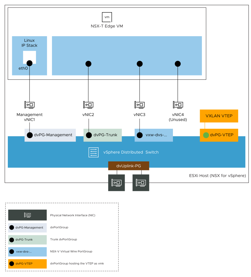
During deployment of Edge node (EN1), select the VDS port groups (networks) for the Edge interfaces as follows.
| Edge Interface | Source Network | Destination Network |
|---|---|---|
| vNIC1 | Network 0 | dvPG-Management |
| vNIC2 | Network 1 | dvPG-Trunk |
| vNIC3 | Network 2 | vxw-dvs-36-virtualwire-1-sid-10600-Vwire-1 |
| vNIC4 | Network 3 | Not used for this bridging example |
Figure below shows the logical view of the vNIC configuration on the NSX Edge VM.