


Add the N-VDS switches on the NSX Edge VM that you have deployed on the NSX-V prepared host.
- Logical View of N-VDS Switches on the NSX Edge VM
-
Following figure shows a logical view of the N-VDS switches on an
NSX Edge VM (EN1) that is deployed on an
NSX-V prepared host.
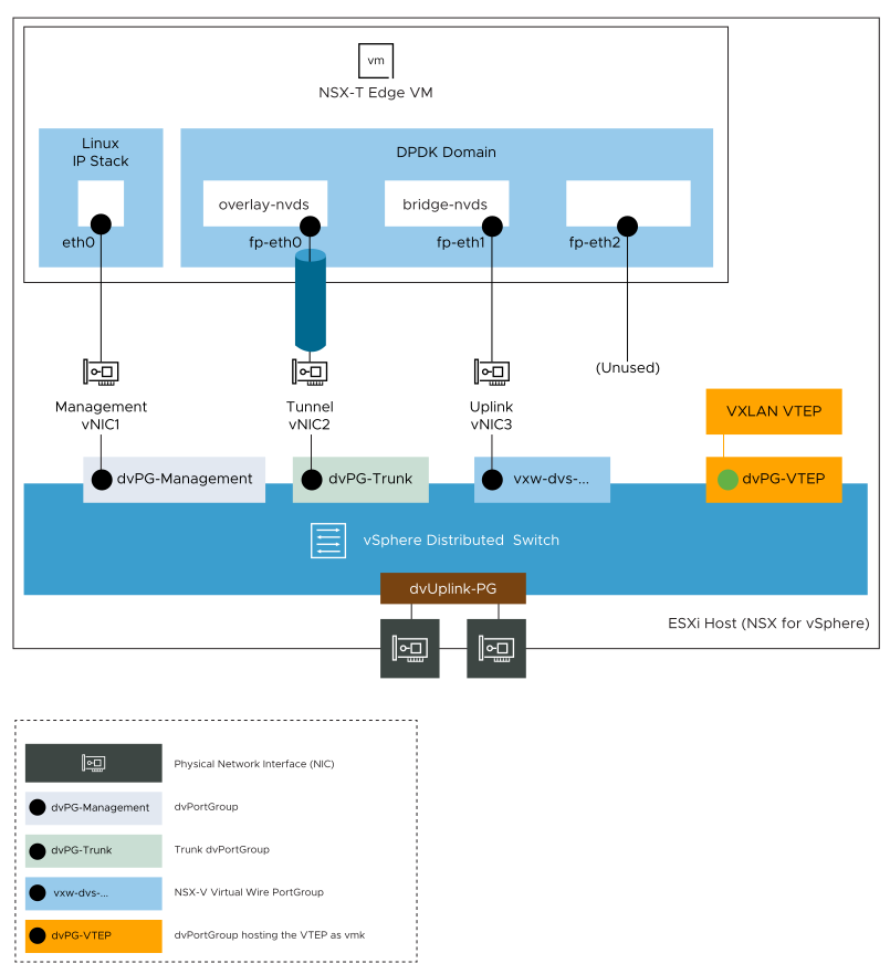
As this topic is focused on configuring the Edge VM for bridging, the port groups for vMotion, Storage, VMkernel interfaces, and so on, are not shown.
NSX Edge VM (EN1) is a transport node in two transport zones: Overlay-TZ and VLAN-TZ. This Edge VM is used for bridging and it has four vNICs. However, for this bridging example, three vNICs are used:- vNIC1 is dedicated to the management traffic.
- vNIC2 is the uplink of the N-VDS switch named overlay-nvds. This Edge switch is attached to the overlay transport zone and used for tunneling overlay traffic.
- vNIC3 is the uplink of the N-VDS switch named bridge-nvds. This Edge switch is attached to the VLAN transport zone. vNIC3 is directly connected to the virtual wire port group that you want to bridge.
In this example, the virtual wire port group on the vSphere Distributed Switch VDS-1 is vxw-dvs-36-virtualwire-1-sid-10600-Vwire-1.
An NSX Edge VM has four internal interfaces: eth0, fp-eth0, fp-eth1, and fp-eth2. Eth0 is reserved for management, while the other interfaces are assigned to Data Plan Development Kit (DPDK) Fast Path. The fp-eth interfaces are connected to physical ToR switches for north-south connectivity and to provide NSX overlay tunneling. You have complete flexibility in assigning the Fast Path interfaces (fp-eth) for overlay connectivity or external connectivity.
In this example, because the NSX Edge VM is used for L2 bridging, fp-eth1 interface is not connected to the physical ToR switch, but it is connected to the virtual wire port group on VDS-1 for the Vwire-1 Logical Switch. The fp-eth interfaces are configured as follows:- fp-eth0 is assigned for overlay traffic.
- fp-eth1 is assigned for external traffic (connected to the virtual wire port group for Vwire-1 Logical Switch)
- fp-eth2 is unused.
- NSX Edge node that serves as the bridge has its own Tunnel Endpoint (TEP) and does not have to be on an NSX prepared host.
- The VXLAN Tunnel Endpoint (VTEP) on an NSX-V prepared host decapsulates the VXLAN frames before the frames reach the Edge VM. That is, the frames that reach the NSX Edge VM are not encapsulated with VXLAN.
To configure the Edge Tunnel End Point (TEP) in the overlay-nvds switch configuration, both static IP list and IP pool are supported. In this bridging example, an IP pool is used.
Prerequisites
Create an IP pool, for example Edge_TEP_Pool.
For detailed instructions, see Create an IP Pool for Edge Tunnel End Points.
Procedure
- For this bridging example, create two uplink profiles that define how the two N-VDS switches on the NSX Edge VM (EN1) connect to the physical network.
- From a browser, log in with admin privileges to an NSX Manager in your NSX environment at https://nsx-manager-ip-address.
- Click .
- Specify the properties of the uplink profile to use for the bridge-nvds.
Example: uplink profile for bridge-nvds
Option Description Name nsx-edge-nic-bridge-uplink-profile Transport VLAN 0 MTU 1600 Teaming Policy Failover Order (Default teaming) - On similar lines, add another uplink profile to use for the overlay-nvds and specify its properties.
Example: uplink profile for overlay-nvds
Option Description Name nsx-edge-nic-overlay-uplink-profile Transport VLAN Edge TEP VLAN Replace Edge TEP VLAN with a VLAN ID that is preferably different from the VXLAN VTEP VLAN.
MTU 1600 Teaming Policy Failover Order (Default teaming)
- Add the N-VDS switches on the NSX Edge VM for overlay transport zone and VLAN transport zone.
- Go to the NSX Manager in your NSX environment.
- Click .
- Click the Edge transport node, and then click Edit.
For example, click EN1.
- Click Add Switch and define the N-VDS switch properties to attach the Edge VM to the overlay transport zone.
Example:
Option Description Edge Switch Name overlay-nvds Transport Zone Overlay-TZ Uplink Profile nsx-edge-nic-overlay-uplink-profile IP Assignment (TEP) Use IP Pool IP Pool Edge_TEP_Pool Uplink fp-eth0 If you want to configure static IP addresses for Edge TEP instead of using an IP pool, in the IP Assignment (TEP) drop-down menu, select Use Static IP List. - Again click Add Switch and define the N-VDS switch properties to attach the Edge VM to the VLAN transport zone.
Example:
Option Description Edge Switch Name bridge-nvds Transport Zone VLAN-TZ Uplink Profile nsx-edge-nic-bridge-uplink-profile Uplink fp-eth1 Although the bridge-nvds switch is attached to the VLAN-TZ, the Edge internally uses the fp-eth1 interface to connect directly to the VXLAN Logical Switch (Vwire-1) in NSX-V.
