You must first set up your infrastructure and then configure your environment for Gateway Security.

1. Deploy NSX Edge Transport Node

You must first deploy the NSX edge transport node.

Prerequisites

You have deployed the NSX Manager and configured the valid licenses.

Procedure

  1. From a browser, log in with admin privileges to an NSX Manager at https://<nsx-manager-ip-address> or https://<nsx-manager-fqdn>.
  2. Select System > Fabric > Nodes > Edge Transport Nodes > Add Edge Node.

    Add edge transport node

  3. Type a name for the NSX Edge.
  4. Type the Host name or FQDN in the format subdomain.example.com.
  5. Select the form factor for the NSX Edge VM appliance.
  6. To customize CPU and memory allocated to an NSX Edge VM appliance, tune the following parameters. However, for maximum performance NSX Edge VM appliance must be assigned 100% of the available resources.
    Caution: If you customize resources allocated to the NSX Edge VM, turn back the reservation later on to 100% to get maximum performance.
    Option Description
    Memory Reservation (%)

    Reservation percentage is relative to the pre-defined value in the form factor.

    100 indicates 100% of memory is reserved for the NSX Edge VM.
    If you enter 50, it indicates that 50% of the allocated memory is reserved for the Edge transport node.
    Note: If you want to use NSX Edge VM datapath interfaces in UPT mode, reserve 100% of the allocated memory for the NSX Edge transport node.
    CPU Reservation Priority Select the number of shares to be allocated to an NSX Edge VM relative to other VMs that are contending for shared resources.
    The following shares are for an NSX Edge VM in Medium form factor:
    • Low - 2000 shares
    • Normal - 4000 shares
    • High - 8000 shares
    • Extra High - 10000 shares
    CPU Reservation (MHz)
    Caution: Unless you need fine grained control over CPU reservations, do not use this field. Instead, change CPU reservations from the CPU Reservation Priority field.

    The maximum CPU reservation value must not exceed the number of vCPUs multiplied by the normal CPU operation rate of the physical CPU core.

    If the MHz value entered exceeds the maximum CPU capacity of the physical CPU cores, the NSX Edge VM might fail to start even though the allocation was accepted.

    For example, consider a system with two Intel Xeon E5-2630 CPUs. Each CPU contains ten cores running at 2.20 GHz. The maximum CPU allocation for a VM configured with two vCPUs is 2 x 2200 MHz = 4400 MHz. If CPU reservation is specified as 8000 MHz, the reconfiguration of the VM completes successfully. However, the VM fails to power on.

  7. In the Credentials window, enter the following details.
    • Specify the CLI and the root passwords for the NSX Edge. Your passwords must comply with the password strength restrictions.
      • At least 12 characters
      • At least one lower-case letter
      • At least one upper-case letter
      • At least one digit
      • At least one special character
      • At least five different characters
      • No dictionary words
      • No palindromes
      • More than four monotonic character sequence is not allowed
    • To enable SSH for an administrator, toggle the Allow SSH Login button.
    • To enable SSH for a root user, toggle the Allow Root SSH Login button.
    • Enter credentials for the Audit role. If you do not enter credentials in the Audit Credentials section, the audit role remains disabled.
      Note: After deploying the NSX Edge node, you cannot change the SSH setting for a root user that you set during deployment. For example, you cannot enable SSH for a root user if you disabled it during deployment.
  8. Enter the NSX Edge details.
    Option Description
    Compute Manager Select the compute manager from the drop-down menu.

    The compute manager is the registered in the Management Plane.

    Cluster Designate the cluster the NSX Edge is going to join from the drop-down menu.
    Resource Pool or Host Assign either a resource pool or a specific host for the NSX Edge from the drop-down menu.
    Datastore Select a datastore for the NSX Edge files from the drop-down menu.
  9. Enter the NSX Edge management interface details.
    Option Description
    Management IP Assignment

    This specifies the IP version used for the IP address assigned to the NSX Edge node which is required to communicate with NSX Manager and NSX Controller.

    Select IPv4 Only or IPv4 & IPv6.

    • If you select IPv4 Only, select DHCP or Static IP.

      If you select Static, enter the values for:
      • Management IP: Enter the IP address of NSX Edge in the CIDR notation.
      • Default gateway: Enter the gateway IP address of NSX Edge.
    • If you select IPv4 & IPv6, enter the values for:
      • Management IP: Enter the IP address of NSX Edge in the CIDR notation.
      • Default gateway: Enter the gateway IP address of NSX Edge.
    Management Interface From the drop-down menu, select the interface that connects to the NSX Edge management network. This interface must either be reachable from NSX Manager or must be in the same management interface as NSX Manager and NSX Controller.

    The NSX Edge management interface establishes communication with the NSX Manager management interface.

    The NSX Edge management interface is connected to distributed port groups or segments.

    Search Domain Names Enter domain names in the format 'example.com' or enter an IP address.
    DNS Servers Enter the IP address of the DNS server.
    NTP Servers Enter the IP address or FQDN of the NTP server.

    Enable UPT mode for datapath interface

    Enable Uniform Passthrough (UPT) mode on NSX Edge datapath interfaces to have direct I/O access or passthrough to the virtual network adapter. It improves overall performance of the NSX Edge node.
    Before you enable this field, ensure:
    • NSX Edge hardware version is 20 or vmx-20 or later. Earlier hardware version do not support UPT mode.
    • ESXi host version must be 8.0 or later.
    Caution: To make UPT settings effective on NSX Edge VM virtual network adapters, NSX Manager puts NSX Edge VM into maintenance mode, powers it off and powers it back on again.
  10. Enter the N-VDS information.

    Consider these points before you confirgure vNICs of NSX Edge nodes:

    An N-VDS switch is hosted inside the Edge node VM with four fast path vNICs and one management vNIC.

    • One vNIC is dedicated to management traffic.
    • One vNIC is dedicated to overlay traffic (fp-eth0 DPDK fastpath interface).
    • Two vNICs are dedicated to external traffic (fp-eth1, fp-eth2 DPDK fastpath interfaces).
    Option Description
    Edge Switch Name Enter a name for the switch or keep the default name.
    Transport Zone Select the transport zones that this transport node belongs to. An NSX Edge transport node belongs to at least two transport zones, an overlay for NSX connectivity and a VLAN for uplink connectivity.
    Note: NSX Edge nodes support multiple overlay tunnels (multi-TEP) when the following prerequisites are met:
    • TEP configuration must be done on one N-VDS only.
    • All TEPs must use the same transport VLAN for overlay traffic.
    • All TEP IPs must be in the same subnet and use the same default gateway.
    Uplink Profile Select the uplink profile from the drop-down menu. The available uplinks depend on the configuration in the selected uplink profile.
    Note: NSX Edge nodes support uplink profiles with Failover teaming policy (with single active uplink and no standby) and Loadbalancer Source teaming policy (with multiple active uplinks) only.
    IP Address Type (TEP) Select the IP version to be used for the tunnel endpoint (TEP). The options are IPv4 and IPv6.
    Important: Ensure that the transport node forwarding mode and TEP IP address type are the same. For example, if the transport node forwarding mode is set to IPv6, set the TEP IP address type to IPv6. If they are different, a loss of traffic may result.
    IPv4 Assignment (TEP)

    This field appears when IP Address Type (TEP) is set to IPv4.

    Choose how IPv4 addresses are assigned to the NSX Edge switch that is configured. It is used as the tunnel endpoint of the NSX Edge. The options are:

    • Use IP Pool: Select the IPv4 pool.
    • Use Static IPv4 List: Specify the following fields:
      • Static IP List: Enter a list of comma-separated IPv4 addresses to be used by the NSX Edge.
      • IPv4 Gateway: Enter the default gateway of the TEP, which is used to route packets another TEP in another network. For example, ESXi TEP is in 20.20.20.0/24 and NSX Edge TEPs are in 10.10.10.0/24 then we use the default gateway to route packets between these networks.
      • IPv4 Subnet Mask: Enter the subnet mask of the TEP network used on the NSX Edge.
    IPv6 Assignment (TEP)

    This field appears when IP Address Type (TEP) is set to IPv6.

    Choose how IPv6 addresses are assigned to the NSX Edge switch that is configured. It is used as the tunnel endpoint of the NSX Edge. The options are:

    • Use IP Pool: Select the IPv4 pool.
    • Use Static IPv6 List: Specify the following fields:
      • Static IP List: Enter a list of comma-separated IPv4 addresses to be used by the NSX Edge.
      • IPv6 Gateway: Enter the default gateway of the TEP, which is used to route packets another TEP in another network.
      • IPv6 Subnet Mask: Enter the subnet mask of the TEP network used on the NSX Edge.
    DPDK Fastpath Interfaces / Virtual NICs

    Map uplinks to DPDK fastpath interfaces.

    Starting with NSX release 2.5, single N-VDS deployment mode is recommended for both bare metal and NSX Edge VM. See .

    Starting with NSX 4.0.1, you can map uplinks to DPDK fastpath interfaces that are backed by smartNIC-enabled DVPGs, VLAN logical switches or segments. The prerequisite is to enable UPT mode on NSX Edge VM virtual network adapters. The UPT mode requires at least one DPDK interface to be backed by smartNIC-enabled hardware also known as Data Processing Unit (DPU)-backed networks.

    Note: If the uplink profile applied to the NSX Edge node is using a Named Teaming policy, ensure the following condition is met:
    • All uplinks in the Default Teaming policy must be mapped to the corresponding physical network interfaces on the Edge VM for traffic to flow through a logical switch that uses the Named Teaming policies. See .

    You can configure a maximum of four unique data path interfaces as uplinks on a NSX Edge VM.

    When mapping uplinks to DPDK Fastpath Interfaces, if NSX Edge does not display all the available interfaces (four in total), it means that either the additional interface is not yet added to the NSX Edge VM or the uplink profile has fewer number of uplinks.

    For NSX Edge VMs upgraded from an earlier version of NSX to 3.2.1 or later, invoke the redeploy API call to redeploy the NSX Edge VM. Invoking the redeploy API ensures the NSX Edge VM deployed recognizes all the available datapath interfaces in NSX Manager UI. Make sure the Uplink profile is correctly configured to use additional datapath NIC.

    For more information on configuring NSX Edge DPDK fastpath interfaces, see .

    • For autodeployed NSX Edges (edge nodes deployed from the NSX Manager UI or API), call the redeploy API. The following API is deprecated.
      POST api/v1/transport-nodes/<transport-node-id>?action=redeploy
    • For manually deployed edges (edges deployed using OVA/OVF file from the VMware vCenter UI or API), deploy a new NSX Edge VM. Ensure all the vmx customizations of the old NSX Edge VM are also done for the new NSX Edge VM.

    Performing vMotion on an NSX Edge VM can result in ESXi running out of resources from a shared buffer pool if you create large VMs with multiple vNICs that use large sized ring buffers. To increase the depth of the shared buffer, modify the ShareCOSBufSize parameter in ESXi. To configure buffer size, see https://kb.vmware.com/s/article/76387.

    Note:
    • LLDP profile is not supported on an NSX Edge VM appliance.
    • Uplink interfaces are displayed as DPDK Fastpath Interfaces if the NSX Edge is installed using NSX Manager or on a Bare Metal server.
    • Uplink interfaces are displayed as Virtual NICs if the NSX Edge is installed manually using vCenter Server.
  11. View the connection status on the Transport Nodes page.
    After adding the NSX Edge as a transport node, the Edge Transport Nodes page will show the Configuration status as Success and Node Status as Up in about 10-12 mins.

1.1: Provision NSX Edge Cluster

You should have two edge nodes in an edge cluster for high availability.

Procedure

  1. Add the edge cluster. Go to System > Fabric > Nodes > Edge Clusters and click Add Edge Cluster.
  2. In the Name text box, enter name for the edge cluster. For example, Edge-cluster-1.
  3. Move the created edge node (Edge-1) from the Available to the Selected window, and click Add.

2. Create a Tier-0 or Tier-1 Gateway

Depending on your use case, create a tier-1 or tier-0 gateway.

Procedure

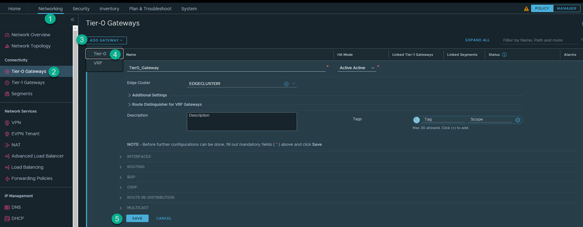
  1. To add a gateway:
    • To add a tier-0 gateway: From the NSX Manager UI, click Networking > Tier-0 Gateways > Add Gateway > Tier-0.

      Add a tier-0 gateway

    • To add a tier-1 gateway: From the NSX Manager UI, click Networking > Tier-1 Gateways > Add Gateway > Tier-1.
  2. Provide the following information.
    Name Enter the name for the gateway. For example, T0-gateway-1.
    Edge cluster Select the created edge cluster. For example, Edge-cluster-1.
  3. Click Save.

    For further details, see NSX Administration Guide.

3. Create Interfaces on Tier-0 or Tier-1 Gateway

NSX gateway has different interface types. Based on the network topology, you can select the required interfaces to connect to the network and provide firewalling for traffic passing through the gateway.
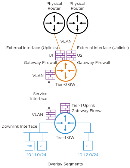
A diagram showing different interface types for NSX gateway.

Tier-0 External Interfaces:

  • Connects to physical router for external connectivity
  • You create this interface on the VLAN segments on the tier-0 gateway

Tier-1 Uplink Interfaces:

  • Connects to gier-0
  • System creates this interface as tier-1 connects to tier-0

Service Interface:

  • Used for providing NSX Services (GFW and other) to non-NSX managed VLAN workloads
  • Connects to VLAN segment
  • Supported on both tier-0 and tier-1

Downlink Interface:

  • Overlay segment Interface on gateway
  • Supported on both tier-0 and tier-1
  • No GFW support
The Gateway Firewall can be mainly used for two scenarios based on how workloads are connected to the network:
  • VLAN connected workloads
  • NSX network overlay segments connected workloads

Each of these scenarios follows slightly different steps to create the network interfaces as described later in this section.

3.1: Create NSX Gateway Firewall Interface for VLAN Connected Workloads

You must perform the following steps to set up your environment.

  1. Create a VLAN segment in NSX.
    1. In the NSX Manager, click Networking > Segments > Add Segment.
    2. Provide the following information.
      Segment Name Enter the name for the segment. For example, VLAN-100.
      Transport Zone Select the default transport zone for the VLAN traffic. For example, nsx-vlan-transportzone.
      VLAN Enter 100.
    3. Click Save.
  2. Create a Service Interface(s) on the tier-0 or tier-1 gateway.
    1. In the NSX Manager, click Networking > Tier-1 Gateways Add Gateway > Tier-1.
    2. Edit the created gateway. For example, T1-gateway-1.
    3. Under Service Interfaces, click Set.
    4. Click Add Interface.
    5. Provide the following information.
      Name Enter the name of the interface. For example, SI-VLAN-100.
      IP Address/Mask Enter an IP address. For example, 192.168.50.12/24.
      Connected To (Segment) Select the configured segment. For example,VLAN-100.
    6. Click Save.

    Create more service interfaces based on the network requirements.

    On tier-0, you have an option to create an external interface, or a service interface based on the connectivity requirement. If an external interface is created, you need to create one external interface per edge, part of the edge cluster.

    As part of the workflow, select the edge node to create that interface, in addition to the mentioned parameters.

For more information, see NSX Administration Guide.

3.2: Create NSX Gateway Firewall Interface for Network Overlay Workloads

Perform the following steps.
  1. Create a Tier-1 Gateway.
    1. Click Networking > Tier-1 Gateways > Add Tier-1 Gateway.
    2. Enter the name for the tier-1 gateway. For example, PROD-Tier1.
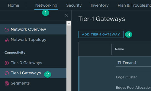
      Add Tier-1 Gateway

    3. Select the tier-0 gateway to create an uplink on the tier-1.
    4. Select the edge cluster for implementing the gateway services.

      After adding tier-1 gateway, add data

    5. Click Save.
  2. Additionally, you should create an overlay segment(s) for connecting workloads. This creates a downlink interface on the gateway and also makes the NSX segments available on the ESXi for network connectivity with the virtual machine.
    1. Click Networking > Segments > NSX > Add Segment.

      Add segment

    2. Provide the following information.
      Name Enter the name for the segment. For example, LS1.1.
      Connectivity Select the configured tier-1 gateway. For example, T1-Tenant1.
      Transport Zone Select the default transport zone for Overlay traffic. For example, nsx-overlay-transportzone.
      Subnets Enter the required subnet. For example, 10.x.x.1/24.
    3. Click Save.
  3. Validate the configured overlay segment is available in the VMware vCenter. In VMware vCenter, go to Host and Clusters, and validate VMs that are created and connected to the configured overlay segment.

For more information, see NSX Installation Guide.